Apparatus and method for evaluation of optical elements

Active Publication Date: 2014-09-11
LUMETRICS
View PDF0 Cites 32 Cited by
  • Summary
  • Abstract
  • Description
  • Claims
  • Application Information

AI Technical Summary

Benefits of technology

[0015]In accordance with the present disclosure, the problem of measuring the physical dimensions and optical performance parameters of a lens or other optical element without contacting the lens or other optical element using a single instrument is solved by an apparatus comprising a low coherence interferometer, a wavefront sensor and an analyzer. The apparatus may further include a computer in signal communication with the low coherence interferometer and the wavefront sensor. The computer may include an algorithm to calculate a plurality of thickness dimensions of the optical element.
[0016]In a first aspect of the invention, an apparatus for measuring the physical dimensions and one or more optical performance parameters of an optical element is provided. The apparatus comprises a low coherence interferometer configured to direct a first beam of light along a defined axis of the optical element. The low coherence interferometer is adapted to measure the optical thickness of the optical element along the defined axis. The apparatus further comprises a wavefront sensor comprised of a light source and a sensor array. The light source is configured to emit a second beam of light surrounding the first beam of light which is directed through the optical element, and onto the sensor array. The wavefront sensor is adapted to measure wavefront deviations due to the presence of the optical element. The apparatus also comprises an analyzer to determine at least one of a physical dimension or an optical performance parameter of the optical element from the interferometer optical thickness measurement and the wavefront sensor wavefront deviations measurement.
[0017]In a second aspect of the invention a method for measuring the physical dimensions and one or more

Problems solved by technology

In the manufacturing of lenses, obtaining fast and accurate measurements of lens dimensions is a challenging problem.
However, this approach is associated with difficulties, arising from the LCI requirements.
Not only is this difficult to

Method used


Image

  • Apparatus and method for evaluation of optical elements
  • Apparatus and method for evaluation of optical elements
  • Apparatus and method for evaluation of optical elements

Examples


Embodiment Construction

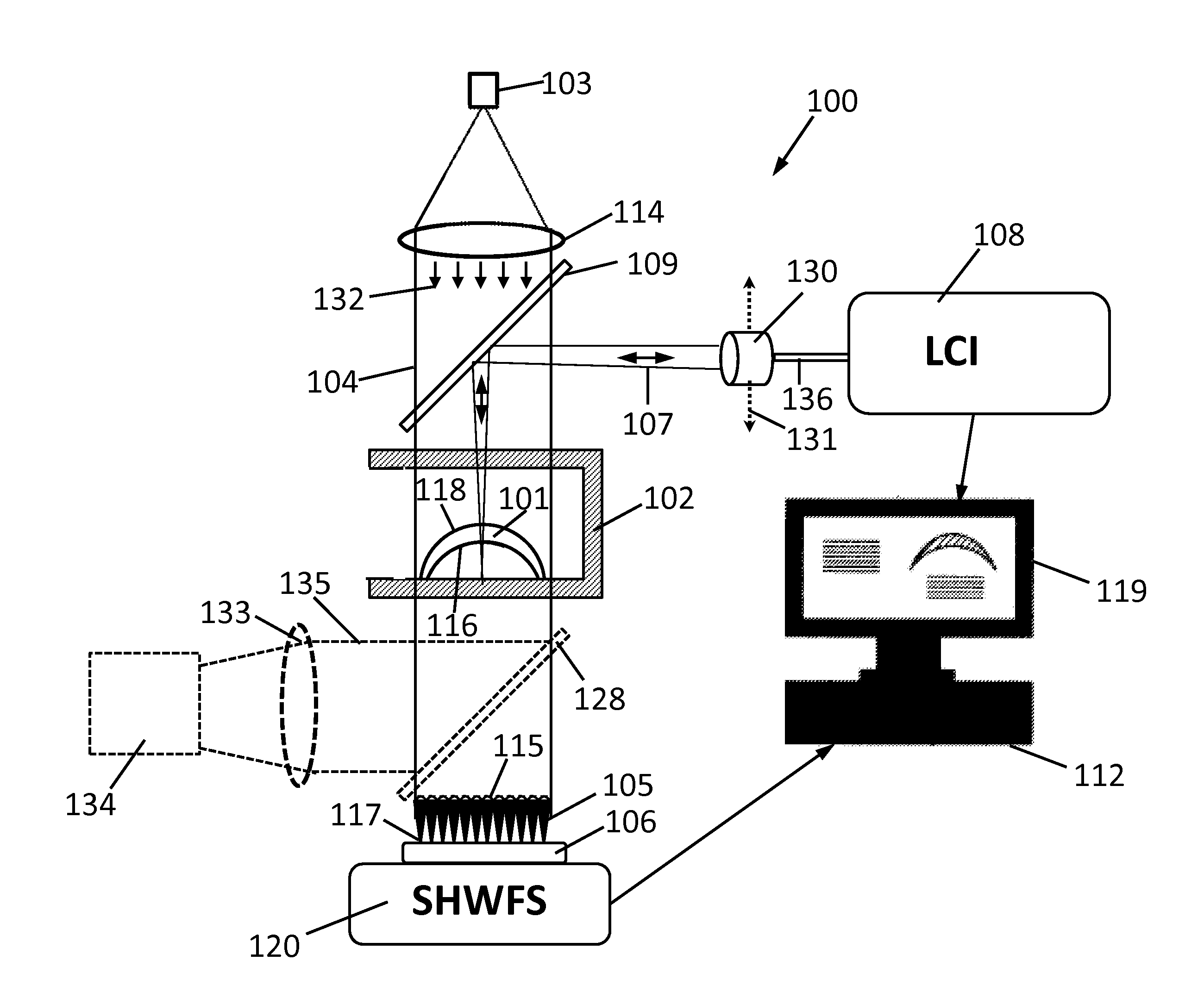
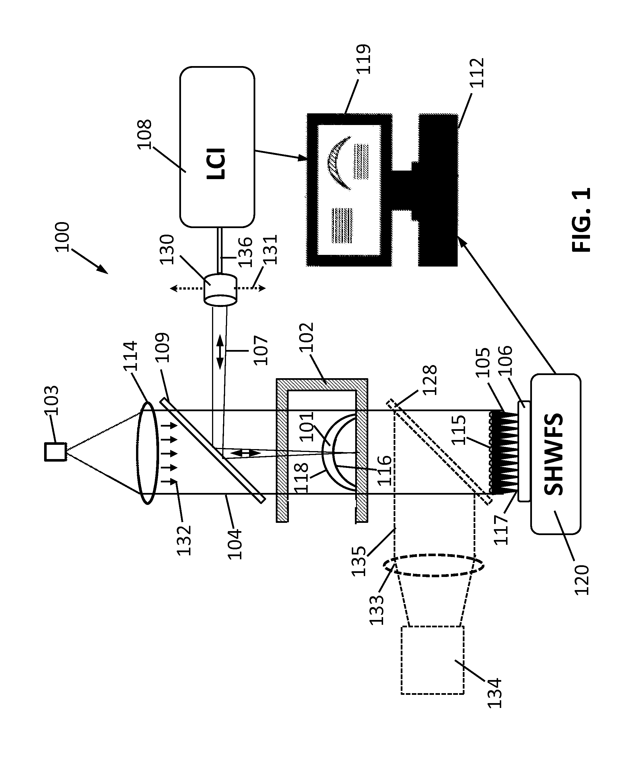
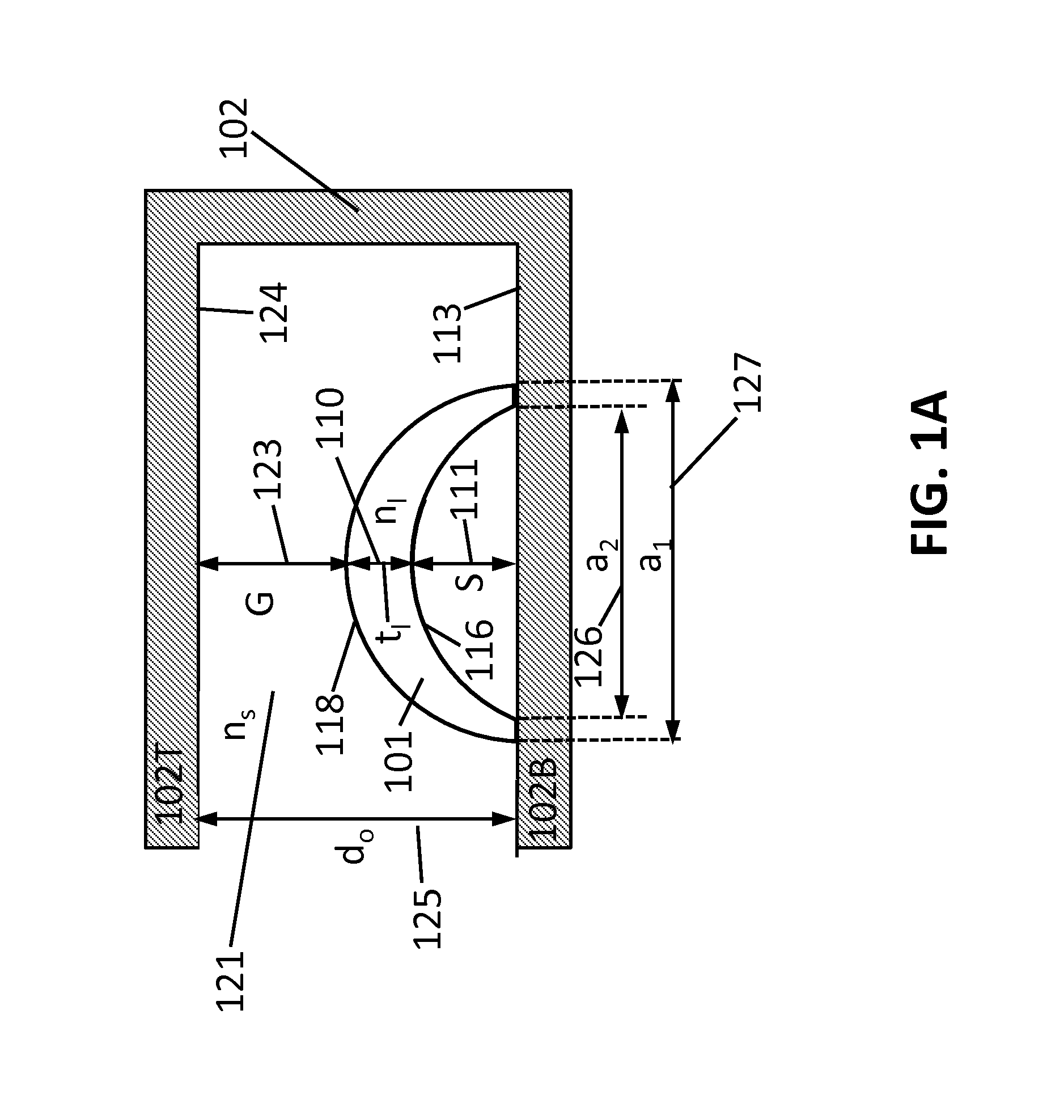
[0033]The present description is directed in particular to elements forming part of, or cooperating more directly with, apparatus in accordance to the invention. For a general understanding of the present invention, reference is made to the drawings. It is to be understood that elements not specifically shown or described may take various form well known to those skilled in the art. Figures shown and described herein are provided in order to illustrate key principles of operation of the present invention and are not drawn with intent to show actual size or scale. Some exaggeration, i.e., variation in size or scale may be necessary in order to emphasize relative spatial relationships or principles of operation.

[0034]In the drawings, like reference numerals have been used throughout to designate identical elements. In the following disclosure, the present invention is described in the context of its use as an apparatus and method for measuring the thickness of lenses. However, it is n...


PUM


Abstract

An apparatus for measuring the optical performance characteristics and dimensions of an optical element comprising a low coherence interferometer and a Shack-Hartmann wavefront sensor comprising a light source, a plurality of lenslets, and a sensor array is disclosed. The low coherence interferometer is configured to direct a measurement beam along a central axis of the optical element, and to measure the thickness of the center of the optical element. The light source of the Shack-Hartmann wavefront sensor is configured to emit a waveform directed parallel to and surrounding the measurement beam of the interferometer, through the plurality of lenslets, and to the sensor array. A method for measuring the optical performance characteristics and dimensions of a lens using the apparatus is also disclosed.

Description

BACKGROUND[0001]1. Technical Field[0002]The present invention relates to the metrology of optical elements, and in particular, the measurement of thickness, optical power and optical aberrations of lenses.[0003]2. Description of Related Art[0004]In the manufacturing of lenses, obtaining fast and accurate measurements of lens dimensions is a challenging problem. This is particularly the case for small low cost high volume lenses, such as contact lenses for the eye. Low-coherence interferometry (LCI) is one measurement technology that may be applied to this measurement problem.[0005]LCI has applications in many fields from medical imaging to glass manufacturing. The low-coherence interferometry is based on using a light source with a very short coherence length. The light is split between two arms of an interferometer and then recombined and directed onto a detector. Interference occurs when the path lengths of the two arms of the interferometer are equal to within the coherence lengt...

Claims


Application Information

Patent Timeline
IPC IPC(8): G01M11/02
CPCG01M11/02G01M11/025G01M11/0235G01M11/0207G01M11/0271G01M11/0278G01M11/0285
Inventor IGNATOVICH, FILIPP V.GIBSON, DONALD S.MARCUS, MICHAEL A.
Owner LUMETRICS
Why Eureka
Try Eureka