Image forming device, density correction method, and non-transistory computer readable storage medium storing program

a technology of density correction and image forming device, which is applied in the field of image forming device, density correction method, and non-transitory computer readable storage medium storing program, can solve problems such as variable print density, and inability to detect accurately. to achieve the effect of reducing excessive correction or level difference in gradation

Inactive Publication Date: 2014-09-11
RICOH KK
View PDF2 Cites 5 Cited by
  • Summary
  • Abstract
  • Description
  • Claims
  • Application Information

AI Technical Summary

Benefits of technology

[0007]For an image forming device that includes a function to correct density by reading a density correction pattern by an internal sensor, which density correction pattern is formed on an image carrier, it is desirable to reduce excessive correction or a level difference in gradation due to detection accuracy of the internal sensor.

Problems solved by technology

For printing using an image forming device, in some cases, a problem is variation in print density due to individual difference, or due to time-dependent deterioration of an individual device.
However, in an image forming device according to related art, detection accuracy is not necessarily good.
When the detection accuracy does not match the density stabilizing performance of the device, excessive correction or a level difference in gradation occurs.

Method used


Image

  • Image forming device, density correction method, and non-transistory computer readable storage medium storing program
  • Image forming device, density correction method, and non-transistory computer readable storage medium storing program
  • Image forming device, density correction method, and non-transistory computer readable storage medium storing program

Examples


Embodiment Construction

[0019]Hereinafter, an embodiment of the present invention is explained by referring to the accompanying drawings.

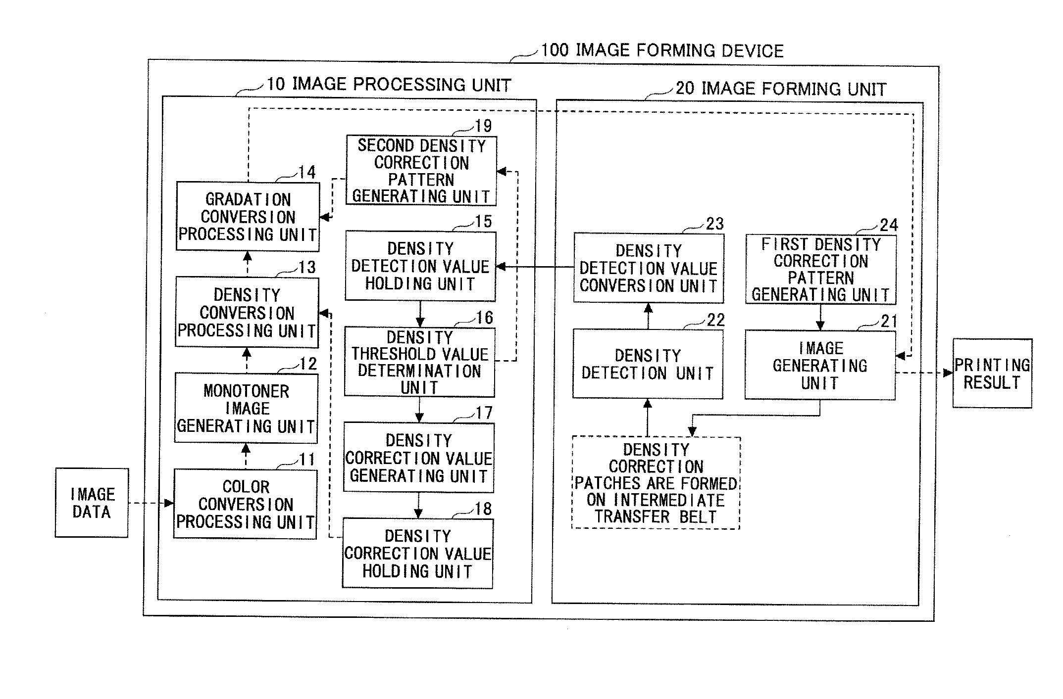
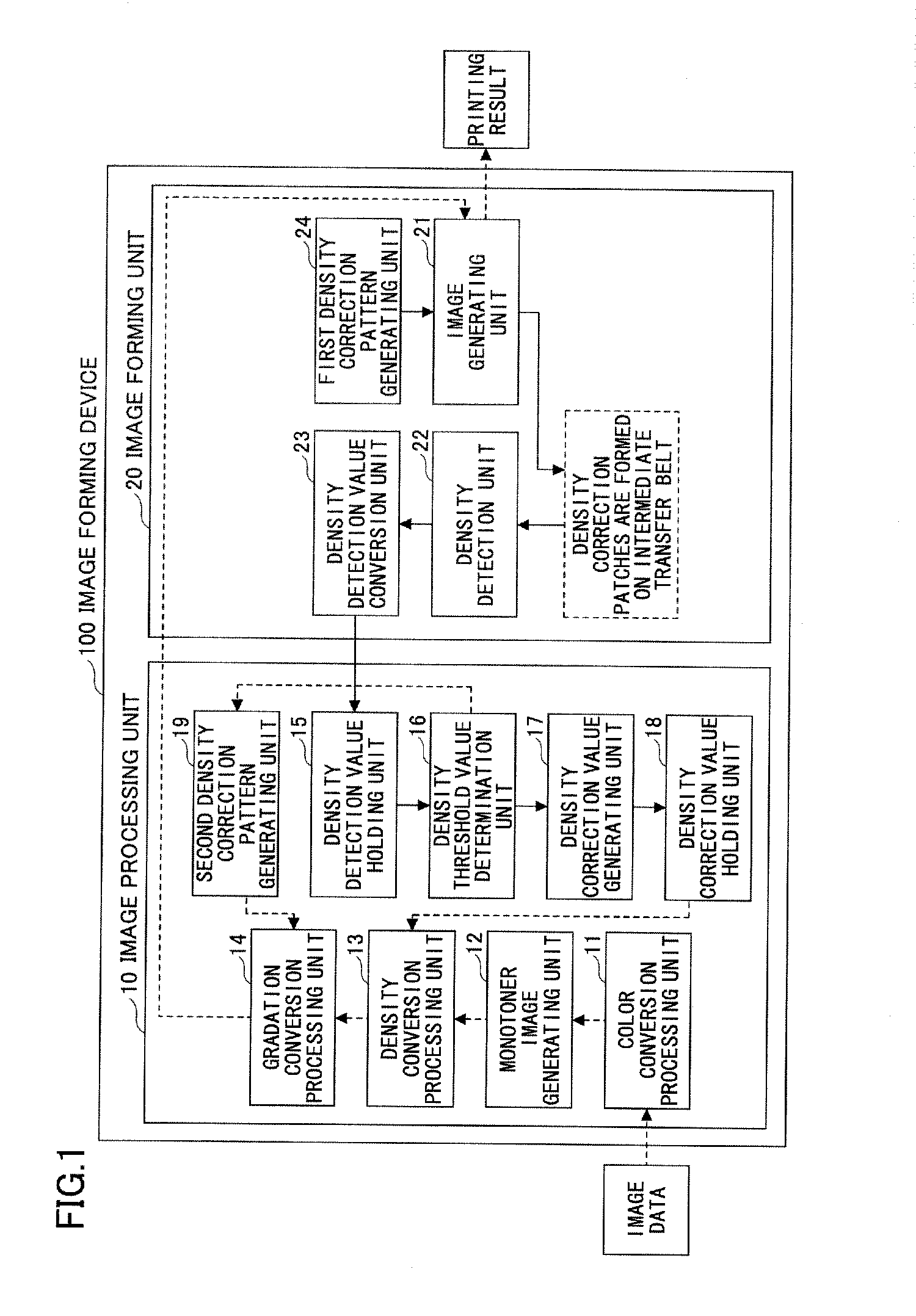
[0020]FIG. 1 is a block diagram showing an example of a configuration of an image forming device 100 according to the embodiment of the present invention. The image forming device 100 is roughly classified into an image processing unit 10 and an image forming unit 20. The image forming device 100 includes an image reading unit (scanner), an operations panel, and the like. However, explanations of these units are omitted here. In addition, for example, a personal computer can be connected to the image forming device 100. However, the explanation is omitted in FIG. 1.

[0021]The image processing unit 10 includes, for example, a color conversion processing unit 11; a monotone image generating unit 12; a density conversion processing unit 13; a gradation conversion processing unit 14; a density detection value holding unit 15; a density threshold value determination unit 16; a ...


PUM


Abstract

An image forming device includes a density correction unit that corrects density based on a density detection value of the density correction pattern; a first density correction pattern generating unit that generates a first density correction pattern having low resolution; and a second density correction pattern generating unit that generates a second density correction pattern having high resolution. When a first density detection value of the first density correction pattern is greater than a predetermined threshold value, the density correction unit corrects the density by determining a density correction reflection rate, based on the first density detection value. When the first density detection value is less than or equal to the predetermined threshold value, the density correction unit corrects the density by determining the density correction reflection rate, based on a second density detection value of the second density correction pattern.

Description

BACKGROUND OF THE INVENTION[0001]1. Field of the Invention[0002]The present invention relates to an image forming device such as a digital color copy machine or a pr a density correction method, and a non-transitory computer readable storage medium storing a program. Particularly, the present invention relates to a technique for correcting print density.[0003]2. Description of the Related Art[0004]For printing using an image forming device, in some cases, a problem is variation in print density due to individual difference, or due to time-dependent deterioration of an individual device. For such a problem, a technique has been known such that a density correction pattern is formed on an image carrier, such as a photoreceptor or an intermediate transfer belt; the density correction pattern is read by a density sensor of a device; and density correction is executed by using the read density value.[0005]For example, Patent Document 1 (Japanese Patent No. 4383622) discloses the followin...

Claims


Application Information

Patent Timeline
Patent Type & Authority Applications(United States)
IPC IPC(8): G06K15/02
CPCG06K15/027
Inventor NAKAJIMA, TAKEHIRO
Owner RICOH KK
Why Eureka
Try Eureka