Magnetic power connector and an electronic system using the magnetic power connector assembly

a technology of magnetic power connectors and magnetic connectors, which is applied in the direction of coupling device connections, coupling parts engagement/disengagement, electrical apparatus, etc., can solve the problems of unstable current flowing through the spring, affecting the signal transmission quality, and affecting the contact between the metal pin and the metal cylinder, so as to avoid heating, avoid functional failure, and improve the lifespan of the contact element

Inactive Publication Date: 2014-09-11
SINGATRON TECH HONG KONG CO
View PDF5 Cites 14 Cited by
  • Summary
  • Abstract
  • Description
  • Claims
  • Application Information

AI Technical Summary

Benefits of technology

[0021]Further, a trigger signal can be generated by establishing an electrical connection between a signal contact element and the conductive element in the magnetic power connector so as to achieve the purpose of identification or control, wherein the movable contact element and the signal contact element are in a first electrical connection status when they are electrically connected, and the movable contact element and the signal contact element are in a second electrical connection status when they are electrically disconnected; the purpose of identification or control can be achieved simply by using the electrically connection relationships between the internal elements of magnetic power connector, to avoid the functional failure caused by the damage of the contact element of the matching magnetic connector.
[0022]The present invention discloses an insulation block disposed on the movable contact element to insulate the conductive element and the elastic element. A conductive path can only be formed between the conductive element and the elastic conductive element, therefore avoiding heating and improving the lifespan of the contact element. In addition, the connector and the electronic device can be made waterproof by a sealing member disposed in the gaps of the connector.

Problems solved by technology

However, when the metal pin is forced to move into the space inside the cylindrical shell body, the contact of the metal pin and the metal cylinder may not be stable due to the manufacturing tolerance of the metal pin.
In addition, current flowing through the spring is not stable due to the length and deformation of the spring that causes rapid resistance changes in the spring, thereby affecting the signal transmission quality.
Although, in the Prior Art 2, the pin can maintain direct contact with the electric conduction medium to allow current to flow through the pin to the electric conduction medium without using the spring, because the spring is made of metal, the current will also flow through the spring to the electric conduction medium, which will shorten the lifespan of the spring due to the heat generated by the current flowing through the spring.
In the prior art 3, a functional failure associated with the identification circuitry can occur when the contact of the plug or receptacle is damaged and the signal path cannot be formed.

Method used


Image

  • Magnetic power connector and an electronic system using the magnetic power connector assembly
  • Magnetic power connector and an electronic system using the magnetic power connector assembly
  • Magnetic power connector and an electronic system using the magnetic power connector assembly

Examples


Embodiment Construction

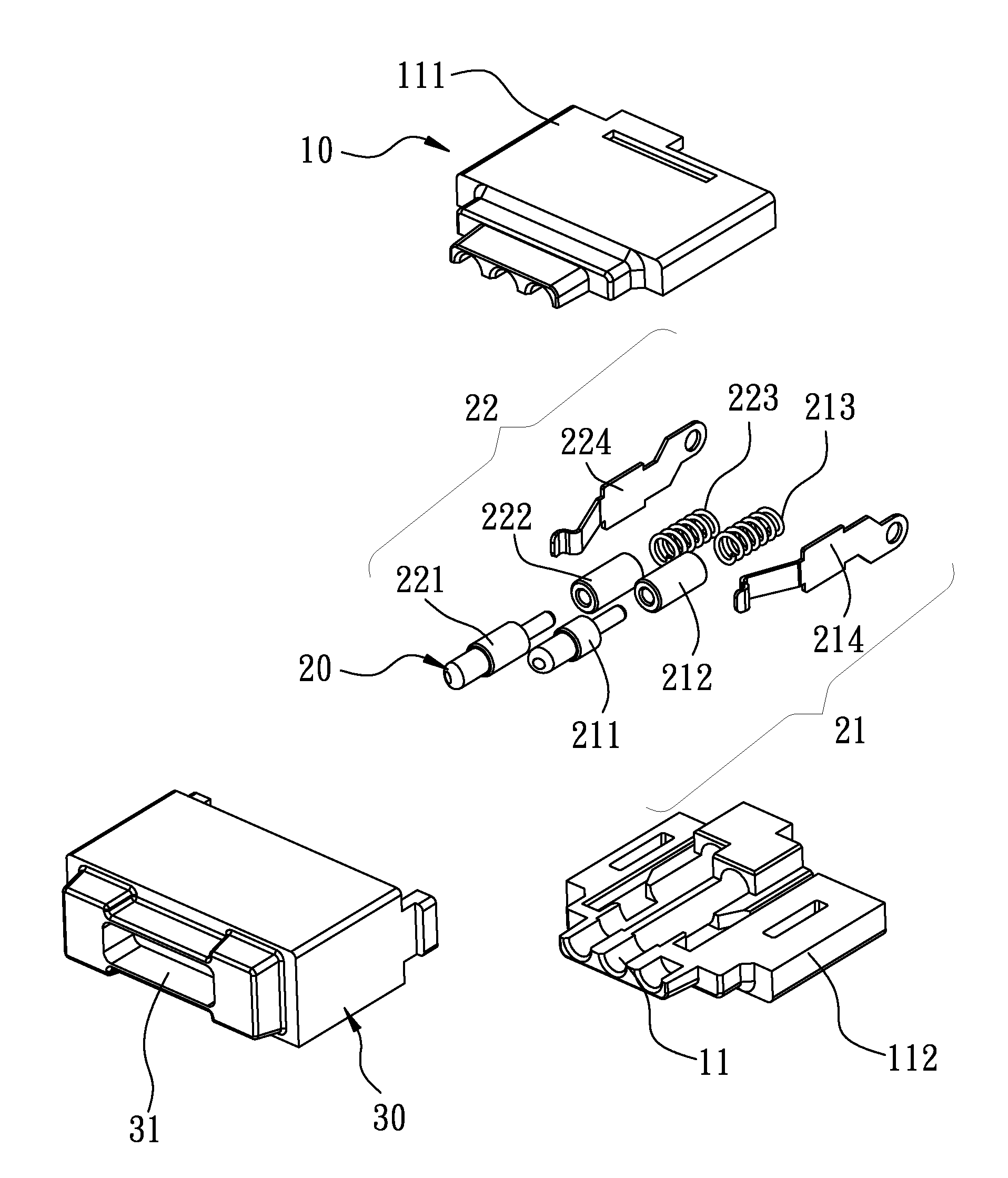
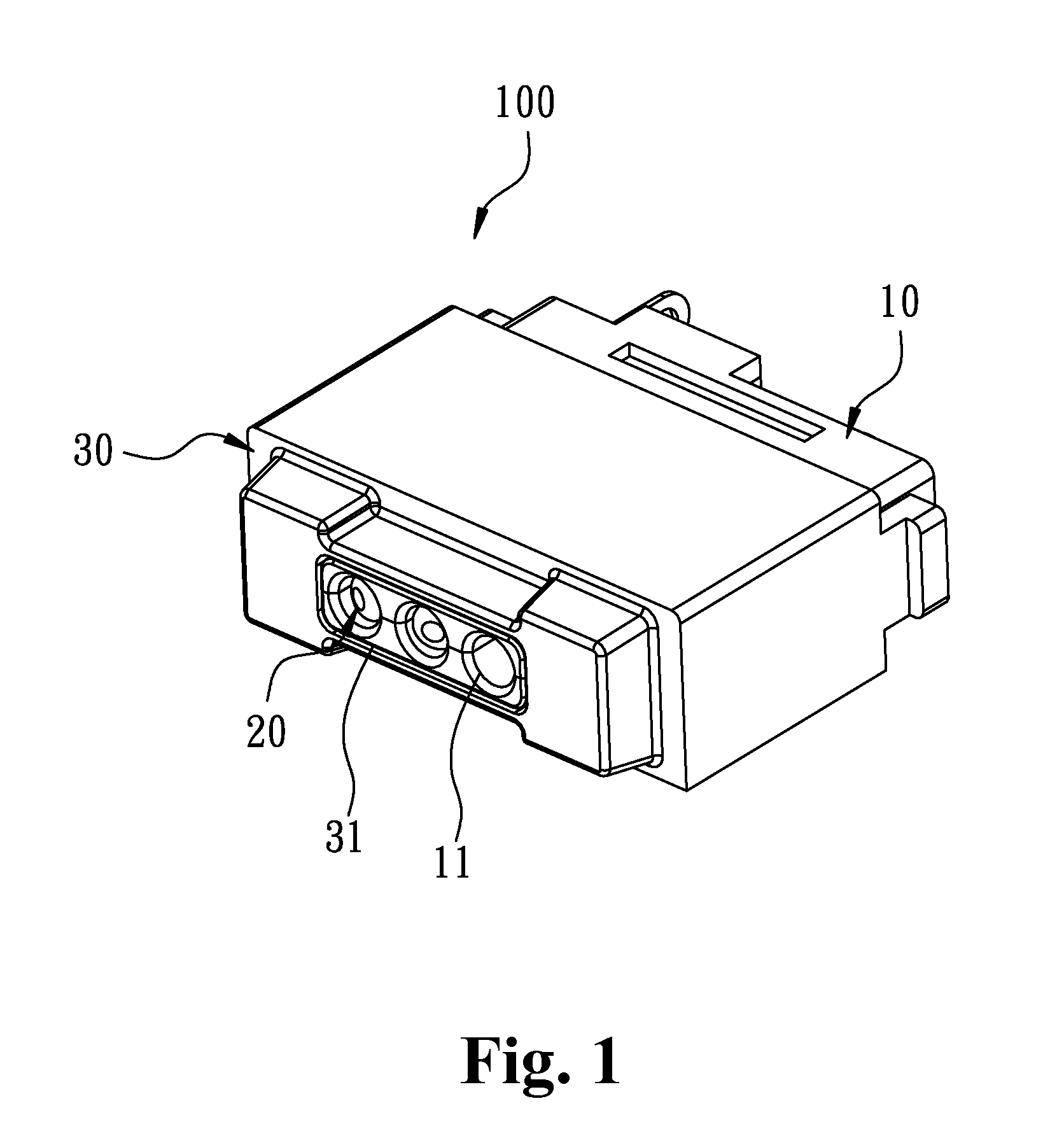
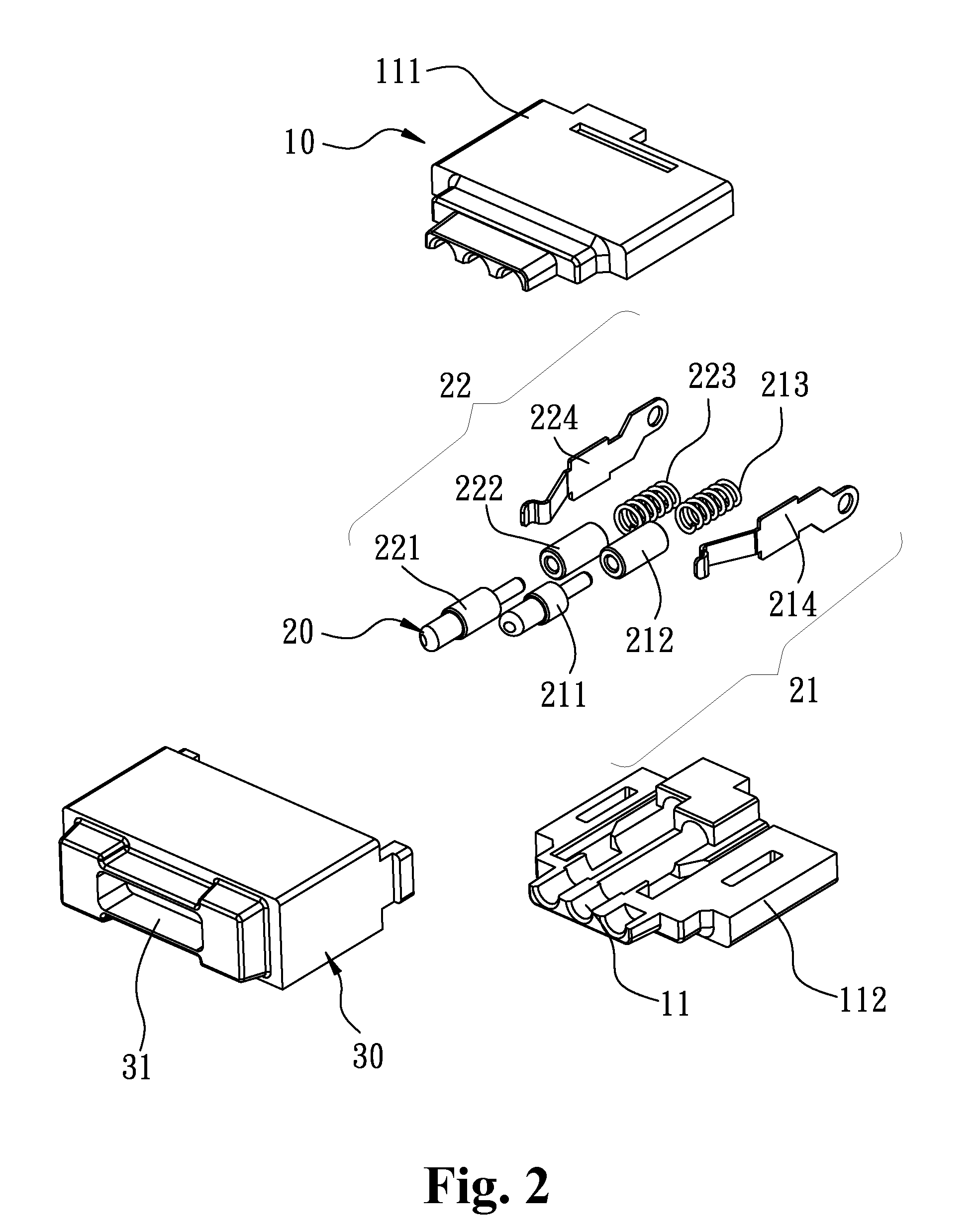
[0037]FIGS. 1 and 2 illustrate the magnetic power connector of the first embodiment of present invention. In FIG. 1 and FIG. 2, a magnetic power connector 100 comprises:

[0038]an insulation body 10 having at least one passage 11. In the current embodiment, the insulation body 10 comprises a first insulation body 111 and a second insulation body 112, the first insulation body 111 and the second insulation body 112 are assembled together and two passages 11 are formed therebetween.

[0039]At least one movable contact element 20 is disposed in the passage 11. In the current embodiment, two movable contact elements 20 are disposed respectively in the passages 11. The movable contact elements 20 define a positive contact element 21 and a negative contact element 22. Each of the positive contact element 21 and the negative contact element 22 respectively includes: a conductive element 211, 221, an insulation block 212, 222, an elastic element 213, 223 and an elastic conductive element 214, 2...


PUM


Abstract

A magnetic power connector and an electronic system using a magnetic power connector are disclosed, wherein a magnetic element of the magnetic power connector is magnetically attracted to a matching magnetic connector to ensure a stable contact. In addition, the electrical conductive path created between the contact elements does not pass through any elastic elements, thereby avoiding heating and improving the lifespan of the elements. Furthermore, sealing can be disposed in the gaps between the connector elements to make the connector waterproof. In addition, a trigger signal can be generated by establishing an electrical connection between a signal contact element and the conductive element in the magnetic power connector so as to achieve the purpose of identification or control, thereby avoiding the functional failure caused by the damage of the contact element of the matching magnetic connector.

Description

BACKGROUND OF THE INVENTION[0001]I. Field of the Invention[0002]The present invention relates to a magnetic connector and in particular to a magnetic connector for electrically connecting an electrical relation to an electronic device.[0003]II. Descriptions of the Prior Art[0004]Please refer to patent document TW M451694 (referred as Prior Art 1 hereafter), wherein a connecting structure is disclosed. The connecting structure includes a metal cylinder, a spring and a metal pin. The metal cylinder comprises a cylindrical shell body and a space inside the shell body to accommodate the spring and the pin, wherein one end of the spring is in contact with the bottom base of the metal cylinder and the other end of the spring is in contact with the metal pin.[0005]In the prior art 1, a conductive path can be formed when the metal pin is in contact with the spring or the metal cylinder. However, when the metal pin is forced to move into the space inside the cylindrical shell body, the conta...

Claims


Application Information

Patent Timeline
Patent Type & Authority Applications(United States)
IPC IPC(8): H01R13/62
CPCH01R13/6205H01R13/2421H01R13/7031
Inventor KUO, RONGHSUN
Owner SINGATRON TECH HONG KONG CO
Why Eureka
Try Eureka