Hose retention system

a technology of retaining system and hose, which is applied in the field of hose retention system, can solve the problems of frailness, too small opening size, and inability to provide multi-hose style clamps in the past, and achieve the effect of quick and easy installation

Inactive Publication Date: 2014-09-18
HICKS THADDEUS R +1
View PDF63 Cites 39 Cited by
  • Summary
  • Abstract
  • Description
  • Claims
  • Application Information

AI Technical Summary

Benefits of technology

[0005]The present invention is a hose anchor adapted for securing individual hoses of auxiliary hydraulic systems on excavators. The present invention is a quick and easy install kit for binding one or more auxiliary hydraulic hose together on a existing tubes of the excavator in an organized manner.
[0006]The problem solved by the present invention is the easy attachment of multiple hoses to a system that has existing tubes in place. In contrast, the installations of the prior art simply use cable ties to attach the hoses to the tubes. Sometimes the cable ties are used in combination with a bulkhead bracket to secure the end of the hoses at the ends of the boom or arm on the excavator. The prior art does not provide any multi-hose style clamps that are useful in this application. The prior art designs only provide for binding together wires and keeping the wires organized. The sizes of the openings are too small and frail to be useful for hoses. Furthermore, merely re-sizing such wire organizers would fail to provide means for attachment of hydraulic or other hoses to existing tubes, which is one aspect of the present invention. Additionally, mere re-sizing of such wire organizers would fail to provide offset spacing and stability of the individual hoses that has been determined by the inventors of the present invention to provide increased space efficiency and protection of the individual hoses in general, and individual hoses of auxiliary hydraulic systems on excavators, in particular.
[0011]According to one embodiment of the hose anchor of the invention, each receiver is formed with a concave inner surface that defines a substantially part-circular notch with the opening thereinto and directed away from the outer surface of the hose support, and the individual intrinsic retainer is formed with a stiffness about the opening that is greater than a stiffness of a wall partially surrounding the opening, which greater stiffness about the opening effectively retains the hose in the receiver.
[0012]According to another embodiment of the hose anchor of the invention, each receiver is instead formed with a concave inner surface defining a substantially part-circular notch with the opening thereinto and directed away from the outer surface of the hose support, and the individual intrinsic retainer includes a ratchet formed of a pawl formed on a flexible stem and a flexible arm having a gear tooth matched to the pawl and positioned adjacent to the opening into the concave inner surface, which ratchet and gear tooth close the opening of the receiver and effectively retain the hose in the receiver.

Problems solved by technology

The prior art does not provide any multi-hose style clamps that are useful in this application.
The sizes of the openings are too small and frail to be useful for hoses.

Method used


Image

  • Hose retention system
  • Hose retention system
  • Hose retention system

Examples


Embodiment Construction

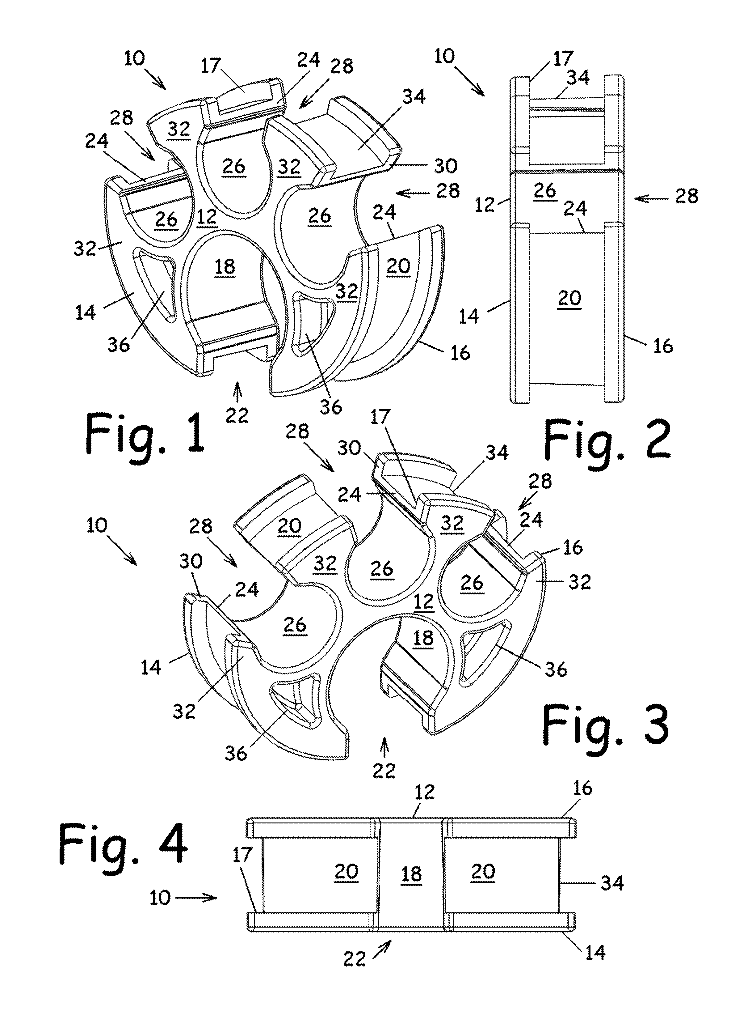
[0025]In the Figures, like numerals indicate like elements.

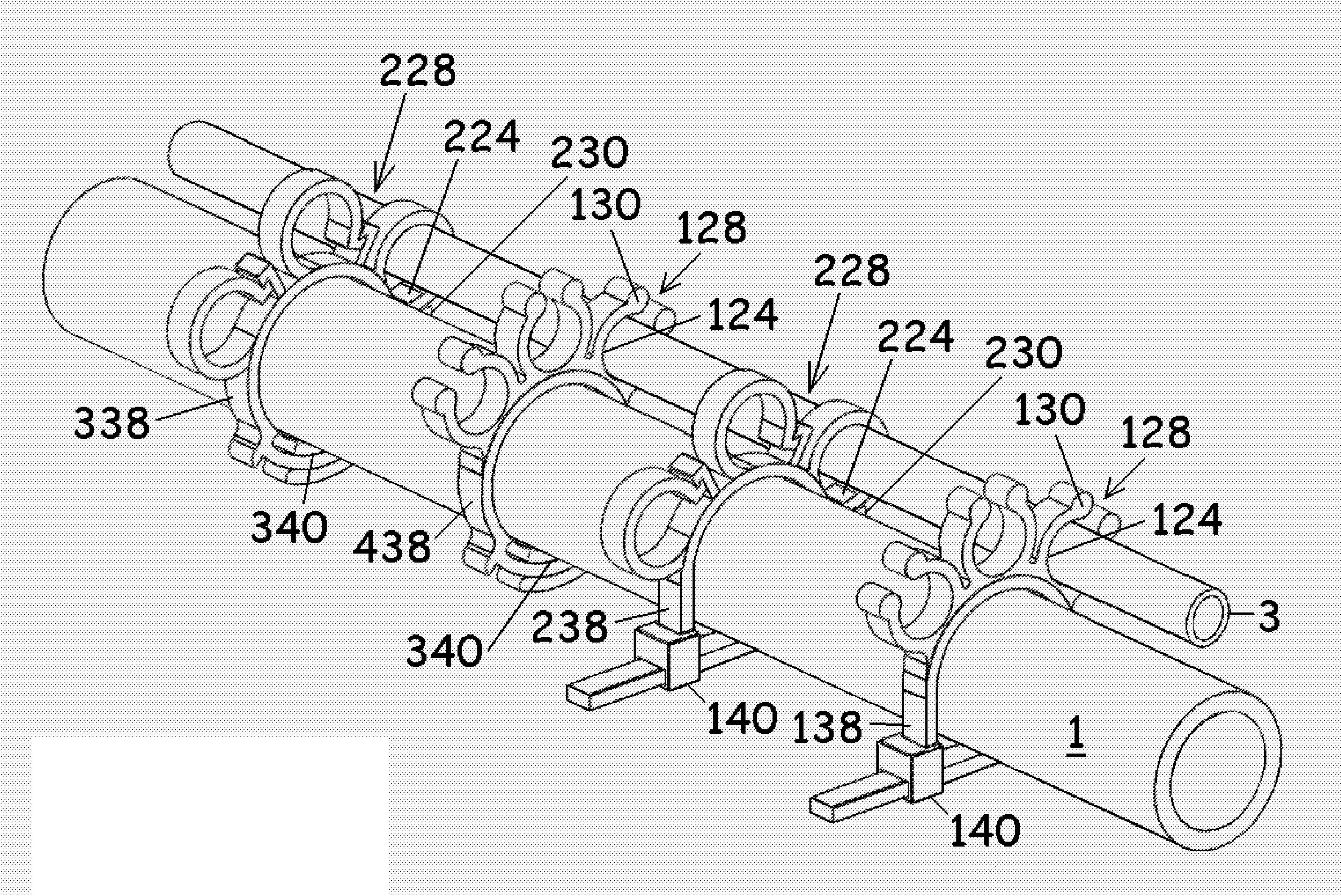
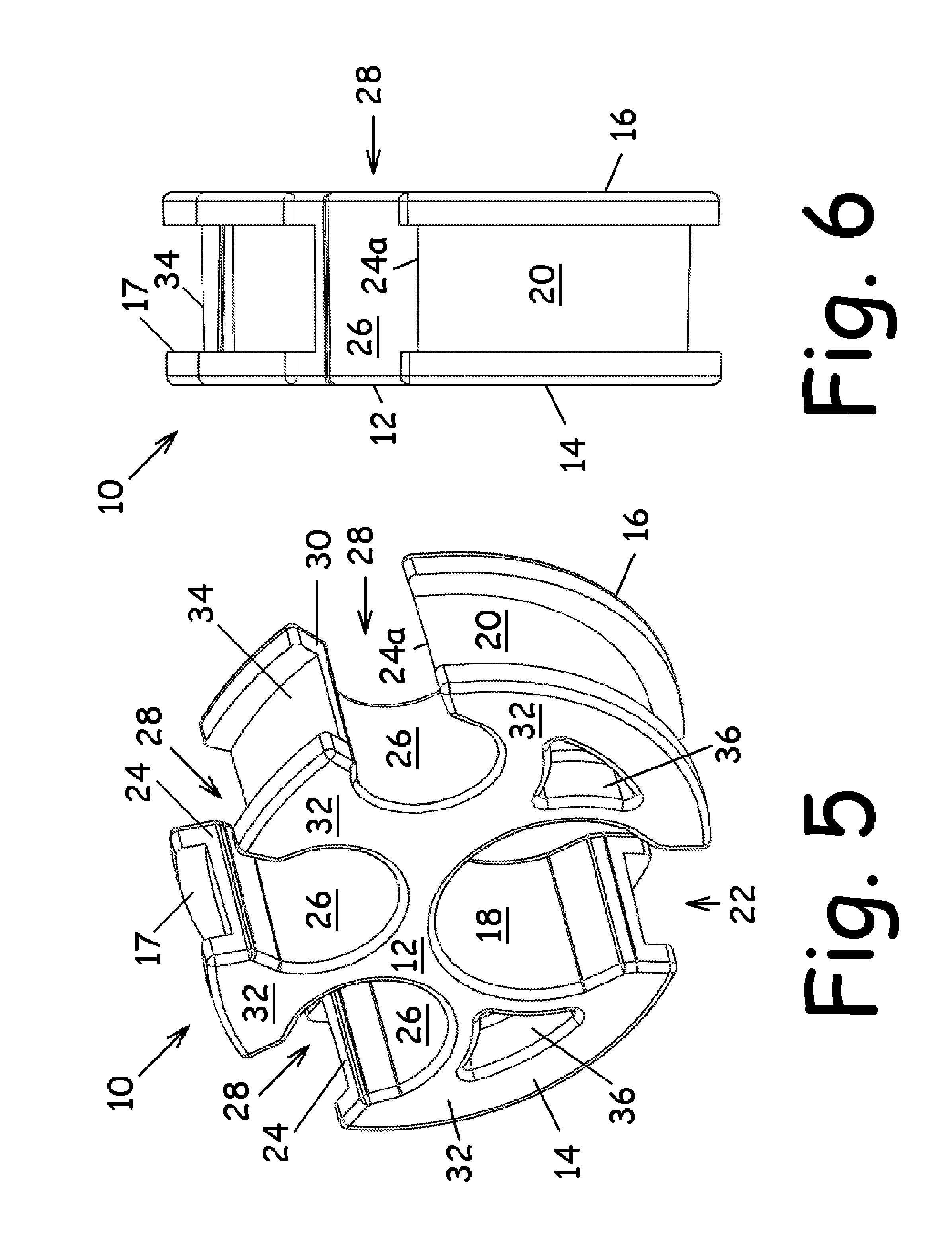
[0026]FIGS. 1-4 illustrate an annular hose support 10 shown in a reel formation having a substantially arcuate disc-shaped core 12 formed sandwiched between a pair of intrinsic flanges 14 and 16 spaced apart on either side thereof, with core 12 being recessed between flanges 14,16 and forming a recess 17 therebetween. Here, hose support 10 is formed with a substantially arcuate inner surface 18 and a substantially arcuate outer surface 20. Inner surface 18 is sized to substantially encompass a tube, such as a pre-existing tube fixed on an excavator or other equipment. As such, outer surface 20 is formed with an opening 22 into inner surface 18, which opening 22 is adapted to permit entry to inner surface 18 of such a tube and subsequently substantially close therearound such tube.

[0027]Outer surface 20 is intrinsically formed with a plurality of individual spaced-apart receivers 24 each adapted for receiving cylindrical elem...


PUM

PropertyMeasurementUnit
stiffnessaaaaaaaaaa
flexibleaaaaaaaaaa
sizeaaaaaaaaaa

Abstract

A hose retainer system that is adapted for securing individual hoses of auxiliary hydraulic systems on excavators. The present invention is a quick and easy install kit for binding several one or more auxiliary hydraulic hoses together on the existing tubes of the excavator in an organized manner.

Description

FIELD OF THE INVENTION[0001]This invention relates generally to a clamp for use in securing one or more hoses individually to existing tubes such as on an excavator or other equipment, and more particularly to securing multiple hoses to existing tubes.BACKGROUND OF THE INVENTION[0002]Cable ties, also known as zip ties or tie-wraps, are generally well-known for easily attaching multiple hoses to a system that has existing tubes in place. For example, attaching hoses of auxiliary hydraulic systems on excavators.[0003]To date, all of the installations known to the inventors simply use cable ties which are tightened around each hose at intervals to attach the hoses of the auxiliary hydraulic systems to the existing tubes on the excavators. Sometimes cable ties are used in combination with a bulkhead bracket to secure the end of the hoses at the ends of the boom or arm on the excavator.[0004]However, the traditional cable tie attachment is a flexible and lacks the ability to maintain the...

Claims


Application Information

Patent Timeline
Patent Type & Authority Applications(United States)
IPC IPC(8): F16L3/10F16M13/02
CPCF16M13/02F16L3/10F16L3/223F16L3/233Y10T29/49947
Inventor HICKS, THADDEUS R.STOY, MICHAEL A.
Owner HICKS THADDEUS R
Why Eureka
Try Eureka