Gas turbine engine with transmission and method of adjusting rotational speed

a technology of transmission and gas turbine engine, which is applied in the direction of turbine/propulsion fuel control, engine fuction, jet propulsion plant, etc., can solve the problems of limiting the efficiency of the engine in such conditions, and the rotation of the compression rotor of the core section is typically larg

Active Publication Date: 2014-09-18
PRATT & WHITNEY CANADA CORP
View PDF120 Cites 42 Cited by
  • Summary
  • Abstract
  • Description
  • Claims
  • Application Information

AI Technical Summary

Benefits of technology

[0005]In one aspect, there is provided a method of adjusting a rotational speed of at least one low pressure compressor rotor of a gas turbine engine having independently rotatable low pressure and high pressure spools, the method comprising: rotating at least one rotor of a high pressure compressor of a core section of the engine with at least one rotor of a high pressure turbine of the core section through the high pressure spool; rotating at least one rotor of a low pressure turbine with a flow of exhaust gases from the high pressure turbine section; rotating the low pressure spool with the at least one rotor of the low pressure turbine; rotating a load of the engine with the low pressure spool; driving a rotation of the at least one low pressure compressor rotor with the low pressure spool through a variable transmission defining a variable transmission ratio between rotational speeds of the at least one compressor rotor and of the low pressure spool; and adjusting the transmission ratio to obtain a desired rotational speed for the low pressure compressor rotor.
[0006]In another aspect, there is provided a method of adjusting rotational speeds of a gas turbine engine havi

Problems solved by technology

In addition, because power demands on the engine vary, for example between take-off and cruise conditions, the turbine and compressor rotors of the core section typically have to rotate at a relatively large range of rotational spee

Method used


Image

  • Gas turbine engine with transmission and method of adjusting rotational speed
  • Gas turbine engine with transmission and method of adjusting rotational speed
  • Gas turbine engine with transmission and method of adjusting rotational speed

Examples


Embodiment Construction

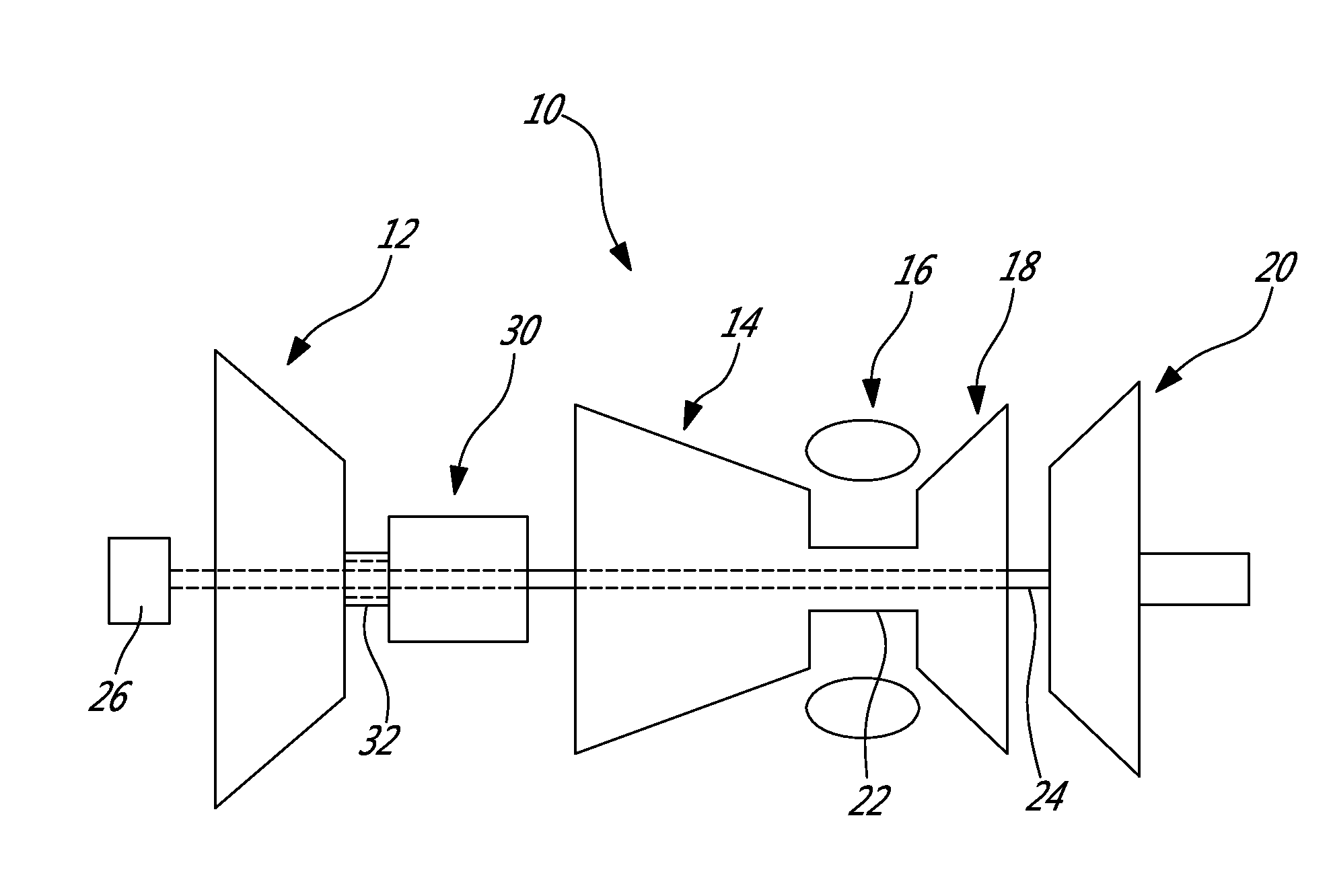
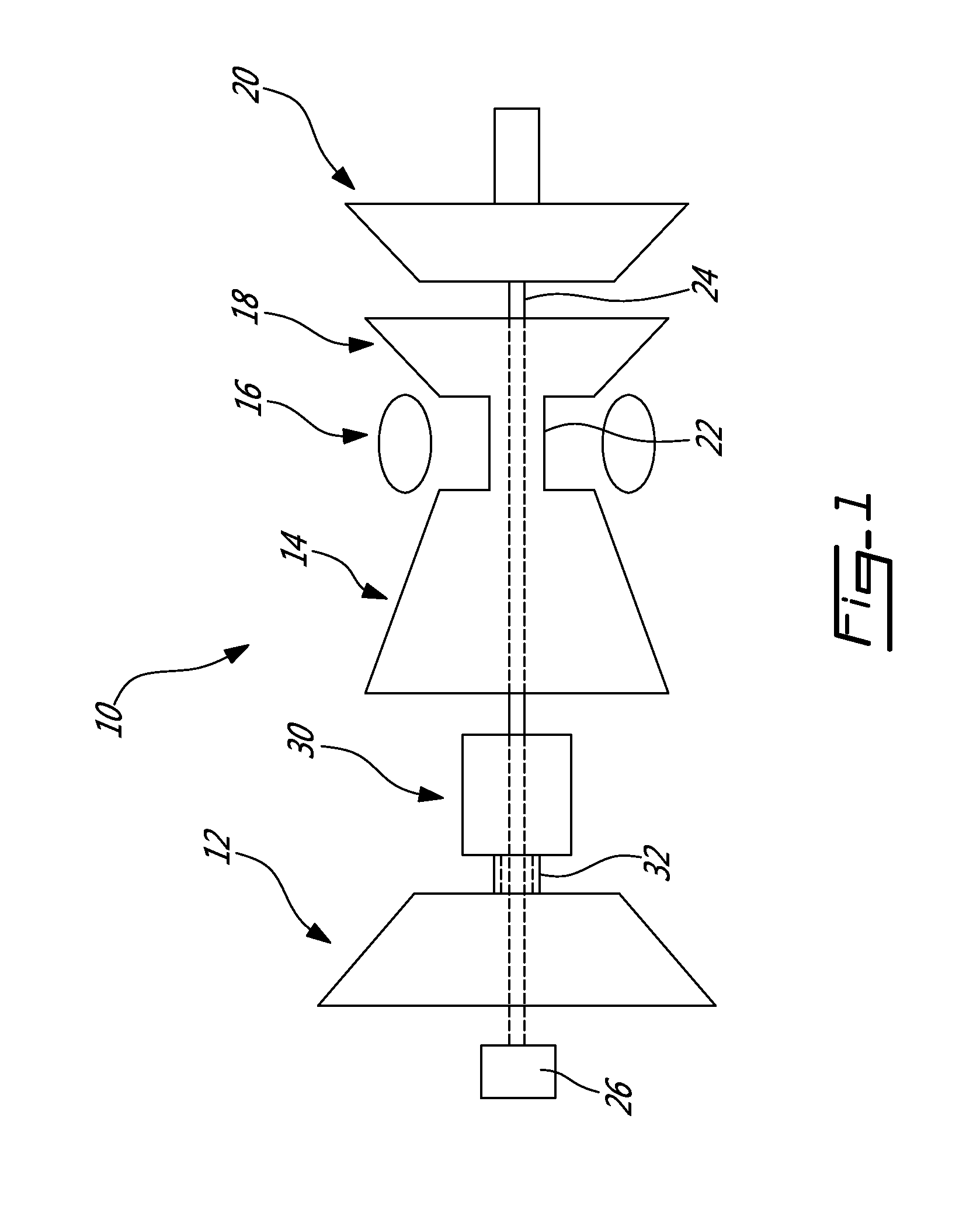
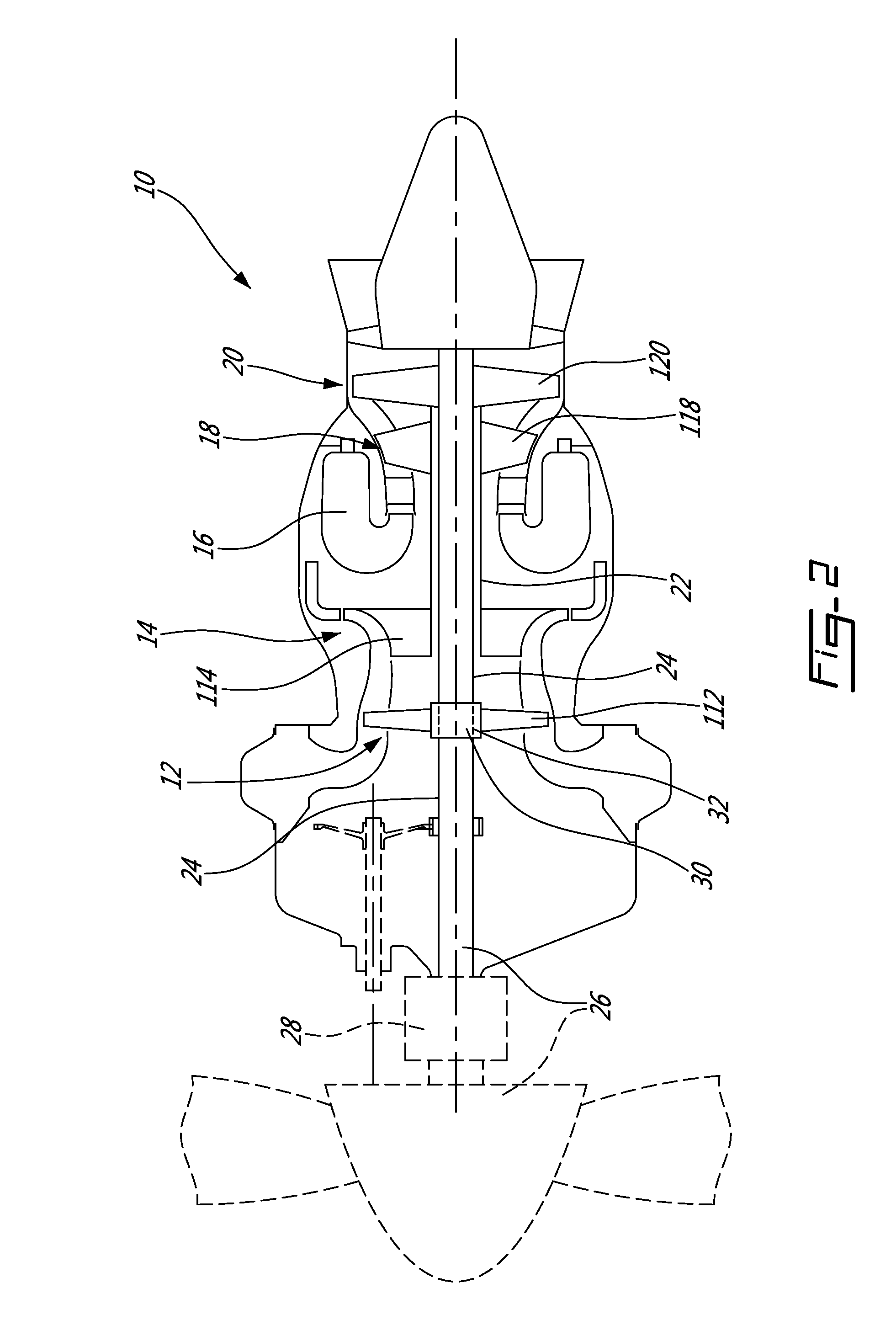
[0017]FIG. 1 schematically illustrates a gas turbine engine 10 of a type preferably provided for use in subsonic flight, generally comprising in serial flow communication a low pressure or booster compressor section 12 and a high pressure compressor section 14 for pressurizing the air, a combustor 16 in which the compressed air is mixed with fuel and ignited for generating an annular stream of hot combustion gases, and a high pressure turbine section 18 and low pressure or power turbine section 20 for extracting energy from the combustion gases.

[0018]The engine 10 includes a high pressure shaft or spool 22 interconnecting the rotors of the high pressure turbine and compressor sections 18, 14, such that a core engine is defined by the high pressure turbine and compressor sections 18, 14 and the combustor 16. The engine further includes a low pressure / power shaft or spool 24 to which the rotor(s) of the low pressure turbine section 20 are connected, such that the rotor(s) of the low p...


PUM


Abstract

A method of adjusting a rotational speed of the low pressure compressor rotor(s) of a gas turbine engine, including rotating the high pressure compressor rotor(s) with the high pressure turbine rotor(s) through the high pressure spool, rotating the low pressure turbine rotor(s) with a flow of exhaust gases from the high pressure turbine, rotating the low pressure spool with the low pressure turbine rotor(s), rotating a load of the engine with the low pressure spool, driving a rotation of the low pressure compressor rotor(s) with the low pressure spool through a variable transmission defining a variable transmission ratio between rotational speeds of the compressor rotor(s) and the low pressure spool, and adjusting the transmission ratio to obtain a desired rotational speed for the low pressure compressor rotor(s). A method of adjusting rotational speeds of a gas turbine engine and a gas turbine engine are also described.

Description

CROSS-REFERENCE TO RELATED APPLICATIONS[0001]This application claims priority from U.S. application Ser. Nos. 13 / 754,045 and 13 / 754,304, both of which were filed Jan. 30, 2013, the entire contents of both of which are incorporated by reference herein.TECHNICAL FIELD[0002]The application relates generally to gas turbine engines and, more particularly, to a gas turbine engine having a transmission.BACKGROUND OF THE ART[0003]In gas turbine engines, the low pressure or booster compressor rotor(s) are typically driven by the low pressure spool either by direct connection thereto such that they rotate at a same rotational speed, or through a fixed ratio gearbox. However, the speed of the low pressure spool is usually determined by the load requirements of the engine, whether the load includes a fan, an output shaft, a propeller, or any other adequate type of rotatable load. In particular for turboprop, turboshaft or APU engines, the rotatable load may be required to rotate at a constant o...

Claims


Application Information

Patent Timeline
IPC IPC(8): F02C3/113
CPCF02C3/113F02C3/107F02C7/36F02C9/56F05D2260/4031
Inventor ULLYOTT, RICHARDMITROVIC, LAZARDUBREUIL, JEANKENNY, STEPHEN CHRISTOPHERBOUCHARD, GUYMEDVEDEV, ILYA B.MORGAN, KEITHKARANJIA, DARIS JEHANGIRYOUSSEF, NASHED AZER
Owner PRATT & WHITNEY CANADA CORP
Why Eureka
Try Eureka