Methods and systems for mini-split liquid desiccant air conditioning

a technology of liquid desiccant air conditioner and mini-split, which is applied in the direction lighting and heating equipment, heating types, etc., can solve the problems of high humidity and cool temperature in the space, unsuitable service of unitary rooftop units, and inability to meet the needs of domestic cooling equipment, etc., to achieve efficient cooling and dehumidification of the air stream

Inactive Publication Date: 2014-09-18
7AC TECH
View PDF9 Cites 70 Cited by
  • Summary
  • Abstract
  • Description
  • Claims
  • Application Information

AI Technical Summary

Benefits of technology

[0008]Provided herein are methods and systems used for the efficient cooling and dehumidification of an air stream especially in small commercial or residential buildings using a mini-split liquid desiccant air conditioning system. In accordance with one or more embodiments, the liquid desiccant flows down the face of a support plate as a falling film. In accordance with one or more embodiments, the desiccant is contained by a microporous membrane and the air stream is directed in a primarily vertical orientation over the surface of the membrane and whereby both latent and sensible heat are absorbed from the air stream into the liquid desiccant. In accordance with one or more embodiments, the support plate is filled with a heat transfer fluid that ideally is flowing in a direction counter to the air stream. In accordance with one or more embodiments, the system comprises a conditioner that removes latent and sensible heat through the liquid desiccant into the heat transfer fluid and a regenerator that rejects the latent and sensible heat from the heat transfer fluid to the environment. In accordance with one or more embodiments, the heat transfer fluid in the conditioner is cooled by a r

Problems solved by technology

However, residential and small commercial buildings often use mini-split air conditioners wherein the condenser is located outside and the evaporator cooling coil is installed in the room or space than needs to be cooled, and unitary rooftop units are not an appropriate choice for servicing those spaces.
This often can result

Method used


Image

  • Methods and systems for mini-split liquid desiccant air conditioning
  • Methods and systems for mini-split liquid desiccant air conditioning
  • Methods and systems for mini-split liquid desiccant air conditioning

Examples


Embodiment Construction

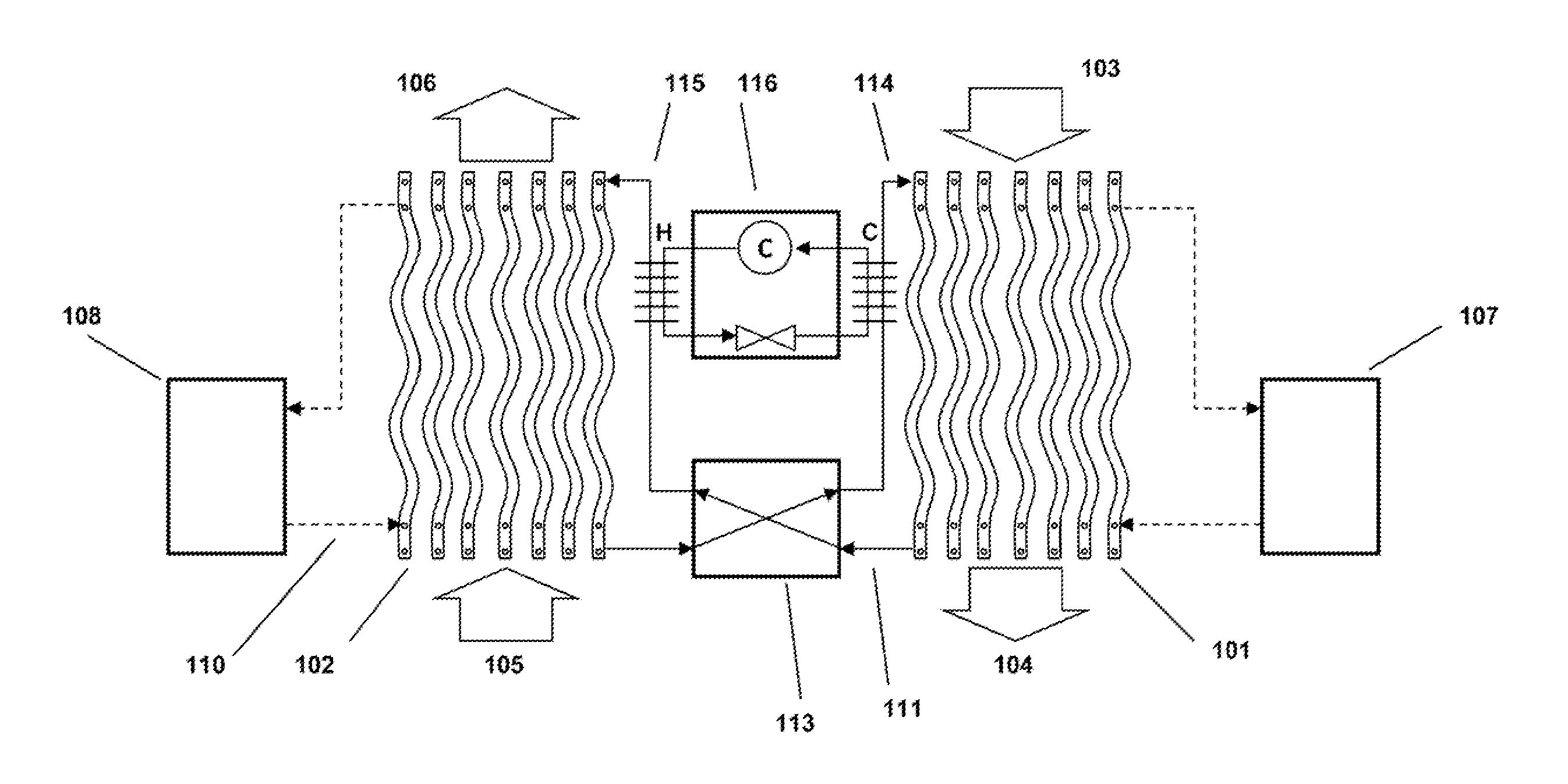
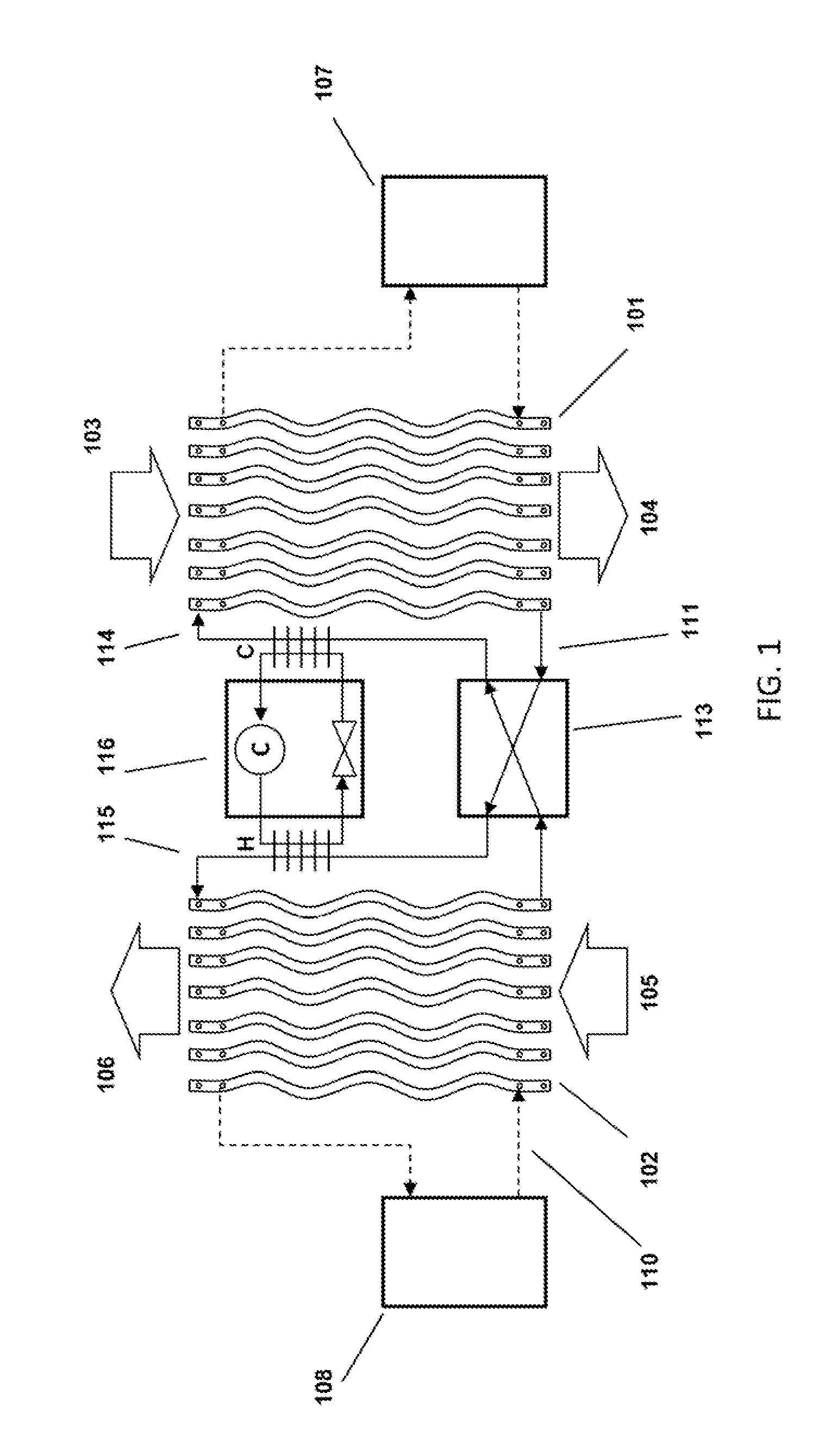
[0026]FIG. 1 depicts a new type of liquid desiccant system as described in more detail in U.S. Patent Application Publication No. US 20120125020, which is incorporated by reference herein. A conditioner 101 comprises a set of plate structures that are internally hollow. A cold heat transfer fluid is generated in cold source 107 and entered into the plates. Liquid desiccant solution at 114 is brought onto the outer surface of the plates and runs down the outer surface of each of the plates. The liquid desiccant runs behind a thin membrane that is located between the air flow and the surface of the plates. Outside air 103 is now blown through the set of wavy plates. The liquid desiccant on the surface of the plates attracts the water vapor in the air flow and the cooling water inside the plates helps to inhibit the air temperature from rising. The treated air 104 is put into a building space.

[0027]The liquid desiccant is collected at the bottom of the wavy plates at 111 and is transpo...


PUM


Abstract

A split liquid desiccant air conditioning system is disclosed for treating an air stream flowing into a space in a building. The split liquid desiccant air-conditioning system is switchable between operating in a warm weather operation mode and a cold weather operation mode.

Description

CROSS REFERENCE TO RELATED APPLICATION[0001]This application claims priority from U.S. Provisional Patent Application No. 61 / 783,176 filed on Mar. 14, 2013 entitled METHODS AND SYSTEMS FOR MINI-SPLIT LIQUID DESICCANT AIR CONDITIONING, which is hereby incorporated by reference.BACKGROUND[0002]The present application relates generally to the use of liquid desiccants to dehumidify and cool, or heat and humidify an air stream entering a space. More specifically, the application relates to the replacement of conventional mini-split air conditioning units with (membrane based) liquid desiccant air conditioning system to accomplish the same heating and cooling capabilities as those conventional mini-split air conditioners.[0003]Desiccant dehumidification systems—both liquid and solid desiccants—have been used parallel to conventional vapor compression HVAC equipment to help reduce humidity in spaces, particularly in spaces that require large amounts of outdoor air or that have large humidi...

Claims


Application Information

Patent Timeline
IPC IPC(8): F24F3/14
CPCF24F3/1411F24F3/1417F24F1/00077F24F3/1429F24F13/30F24F13/20F24F2003/1458
Inventor VANDERMEULEN, PETER F.
Owner 7AC TECH
Why Eureka
Try Eureka