High strength tether for transmitting power and communications signals

a high-strength, communications signal technology, applied in the direction of insulated conductors, power cables, cables, etc., can solve the problems of electrical wires and optical fibers being strained by the tether, and achieve the effects of reducing crimp, reducing crimp, and liberalizing spa

Active Publication Date: 2014-09-18
THREE BEES BRAIDING LLC
View PDF12 Cites 19 Cited by
  • Summary
  • Abstract
  • Description
  • Claims
  • Application Information

AI Technical Summary

Benefits of technology

[0007]The present invention is a tether that utilizes a number of high performance fibers as strength-providing members. Additionally, multiple insulated metal wires, perhaps one uninsulated bleed / ground wire and at least one fiber optic cable are integrated into the tether for transmission of electrical power and optical signals. The novel arrangement of the different components allows for an efficient structure, with a high strength and low weight, in which the effective strain at failure of the signal conducting components is less than or equal to the failure strain of the entire tether. Said differently, the geometry of the current invention allows the strength members to be efficient in load bearing, while conductors elongate without failure using geometric form strain rather than material strain.
[0008]The tether of this invention includes a core of strength members, a compaction layer, fiber optic and electrical conductors, and an abrasion resistant outer layer. The core may be straight, twisted, or in a rope configuration. The preferred embodiment is a twist level low enough to maintain strength and strain to failure, but sufficient to prevent filament separation during winding. The subsequent concentric layers may be braided or wrapped around the core. The preferred embodiment is braiding. The design motivation for the tether is to contain both electrical wires and fiber optic strands, and yet be extremely strong and lightweight.
[0009]The unique arrangement of the cable of the present invention provides a tether that is more easily deployable and reeled in than a conventional net structure. Further, the tether of the present invention may be manufactured by conventional machinery, namely a maypole braider.

Problems solved by technology

The result is that, rather than being shielded from straining, it is expected that the electrical wires and optical fibers will strain with the tether.

Method used


Image

  • High strength tether for transmitting power and communications signals
  • High strength tether for transmitting power and communications signals
  • High strength tether for transmitting power and communications signals

Examples


example 1

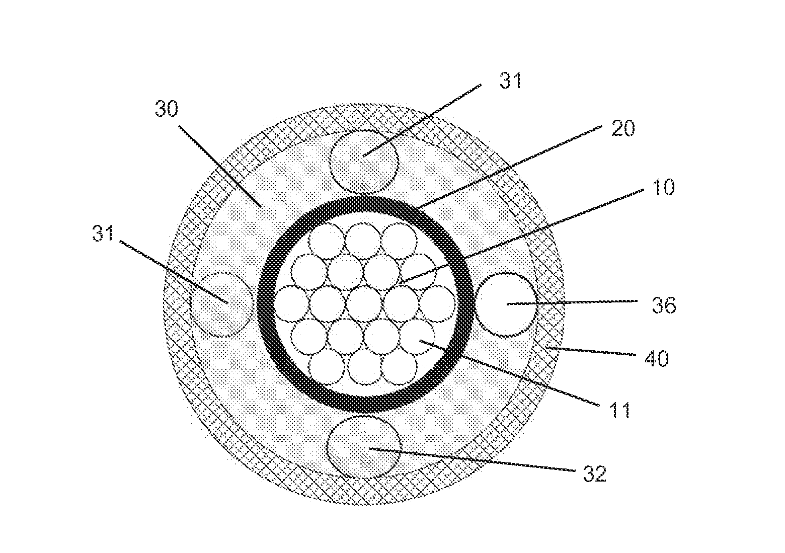
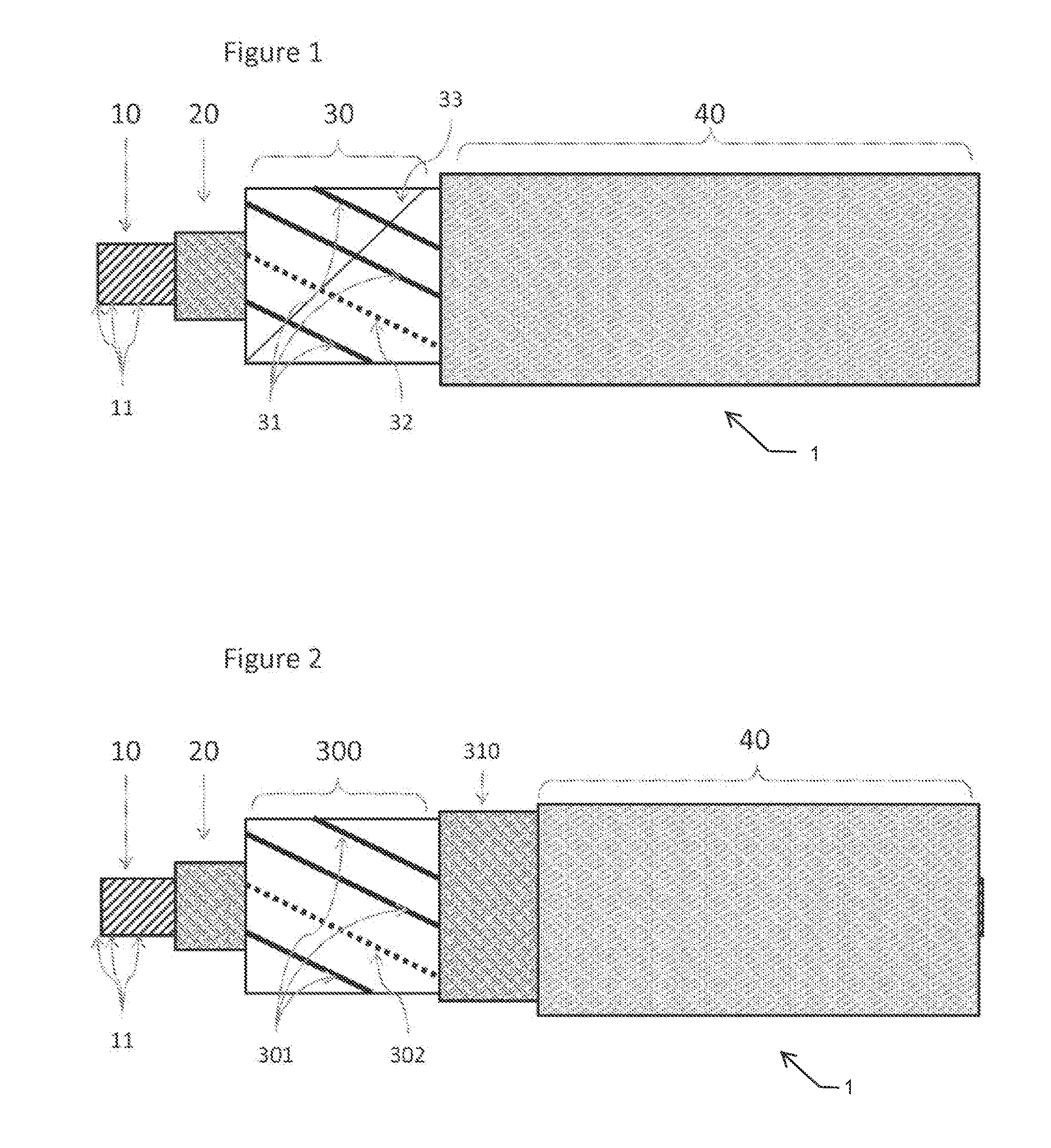
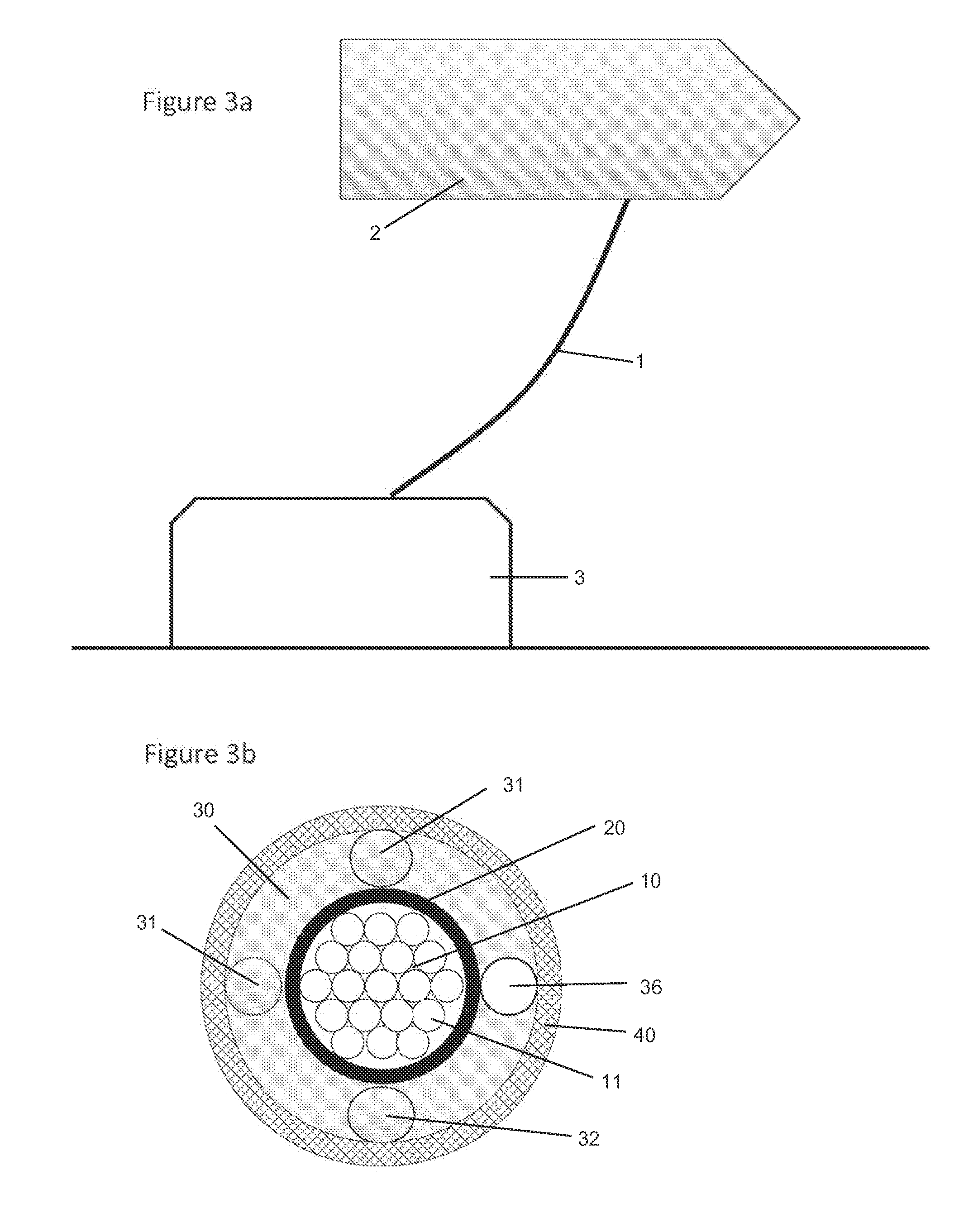
[0036]A tether was constructed as follows:[0037]A single Kevlar™ yarn in the center of the core;[0038]16 yarns twisted around the single central yarn with core twist in the opposite direction from yarn twist;[0039]The pitch of yarn twist in the core of about 0.66 inches;[0040]A tight 12 Kevlar™ yarn braid in the first overbraid;[0041]16 yarn diamond braid, including the fiber optic strand, three electrical conductors and 12 Kevlar (™) yarns in the second overbraid; and[0042]A 16 yarn nylon “carpet yarn” overbraid for protection of the interior components.

The tether as tested to 1000 pounds load without loss of optical or electrical signal carrying capability.

example 2

[0043]A tether was constructed as follows:[0044]A central core of 17 twisted Kevlar™ strands;[0045]A tight overbraid of 16 Kevlar™ strands;[0046]A loose overbraid of 3 electrical conductors, one fiber optic strand, and 12 Kevlar™ strands; and[0047]A protective overbraid of 16 nylon strands.


PUM

PropertyMeasurementUnit
weightaaaaaaaaaa
strengthaaaaaaaaaa
pitch angleaaaaaaaaaa

Abstract

An electro-optical-mechanical tether is presented. The tether is designed to be strong and lightweight, and to transmit both optical signals and electricity. The proposed use relates to airborne devices, in which the tether may transmit electrical power to or from the device as well as enabling communications between the device and the ground. This tether may also be ideal for other aerospace applications and for connections between ships.

Description

BACKGROUND OF THE INVENTION[0001]1. Field of the Invention[0002]This invention relates to a strong, lightweight tether or electro-optical-mechanical (EOM) cable. The tether is designed and primarily used for applications relating to airborne devices, specifically to attach the airborne device to the ground or a structure or vehicle on the ground while also performing other functions. Some of the functions include electrical power transmission either to the airborne device or from the airborne device if it includes a power generator. Electrical wires in the tether also allow for communication via electrical signals, although it is preferred to use the embedded optical fibers for communication. The tether may be used to send control commands to the airborne device, receive feedback from the airborne device, receive, detect or broadcast transmissions or collect surveillance and send it to the ground. The tether also exhibits other features including high strength and light weight, whic...

Claims


Application Information

Patent Timeline
Patent Type & Authority Applications(United States)
IPC IPC(8): H01B7/04D02G3/44H01B9/00B64C39/02B64G1/66
CPCH01B7/043H01B9/005B64G1/66B64C39/022B64G1/648G02B6/4417Y10T29/49826
Inventor BROUGHTON, JR., ROYALL M.BRANSCOMB, DAVID JOHNBEALE, DAVID G.
Owner THREE BEES BRAIDING LLC
Why Eureka
Try Eureka