Lock-up device for torque converter

Active Publication Date: 2014-09-18
EXEDY CORP
View PDF3 Cites 34 Cited by
  • Summary
  • Abstract
  • Description
  • Claims
  • Application Information

AI Technical Summary

Benefits of technology

[0025]According to the present invention as described above, it is

Problems solved by technology

It is difficult for the well-known lock-up device of the multi-

Method used


Image

  • Lock-up device for torque converter
  • Lock-up device for torque converter
  • Lock-up device for torque converter

Examples


first exemplary embodiment

Entire Structure of Torque Converter

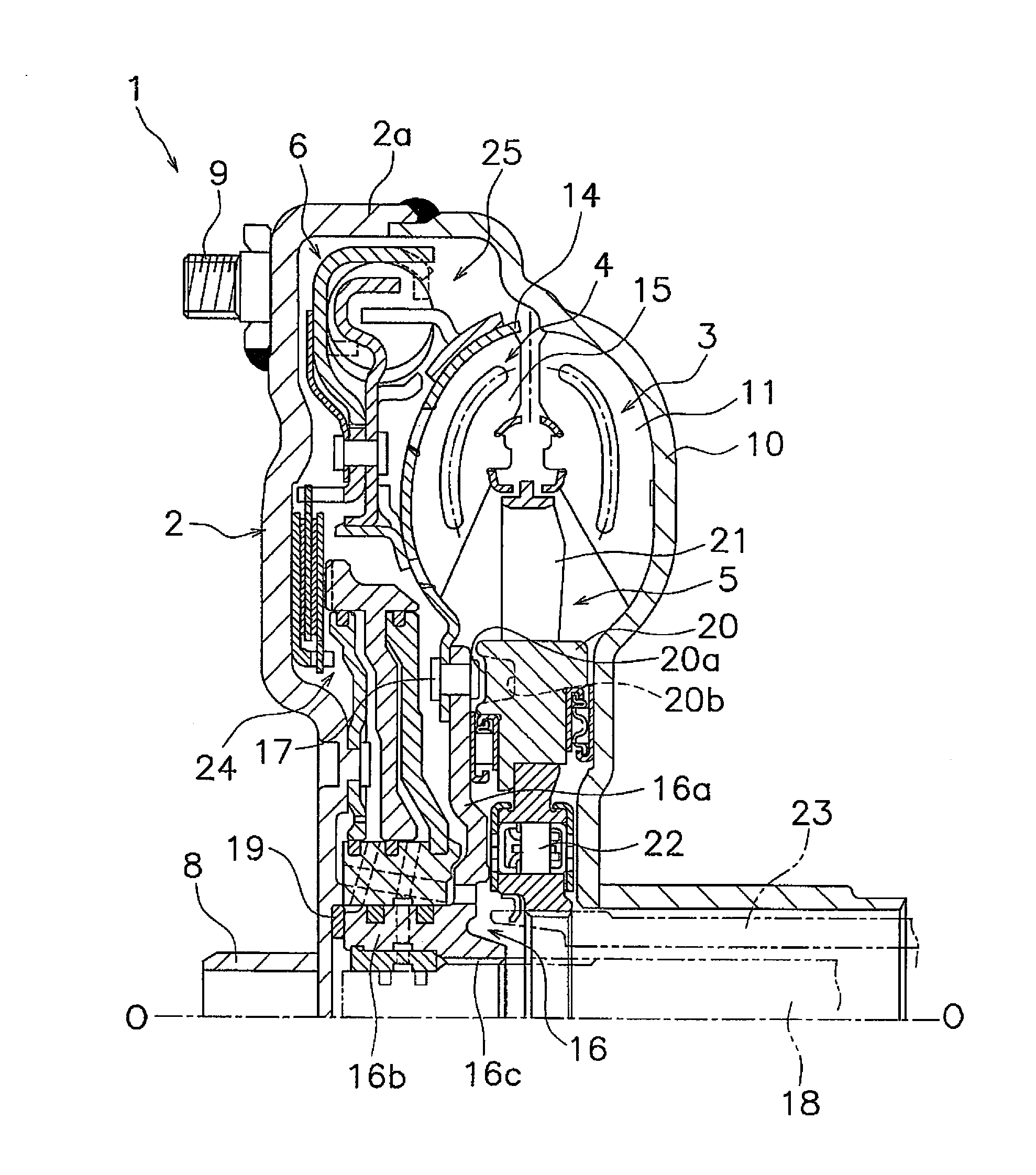
[0036]FIG. 1 is a vertical cross-sectional view of a torque converter 1 employing an exemplary embodiment of the present invention. The torque converter 1 is a device for transmitting torque from a crankshaft of an engine to an input shaft of a transmission. In FIG. 1, the engine (not illustrated in the drawing) is disposed on the left side, whereas the transmission (not illustrated in the drawing) is disposed on the right side. A line O-O depicted in FIG. 1 indicates a rotary axis of the torque converter 1.

[0037]The torque converter 1 mainly includes a front cover 2, a torque converter main body composed of three types of vane wheels (an impeller 3, a turbine 4 and a stator 5), and a lock-up device 6.

Front Cover

[0038]The front cover 2 is a disc-shaped member that a center boss 8 is fixed to the inner peripheral end thereof by welding. The center boss 8 is a cylindrical member extending in the axial direction, and is inserted into a center hole bo...

second exemplary embodiment

[0092]FIG. 8 illustrates another exemplary embodiment of a power transmission plate support member. This power transmission plate support member 70 is composed of a first plate 71 and a second plate 72.

[0093]The first plate 71 is formed in an annular shape, and is composed of a fixation portion 71a, an first axial restriction portion 71b, a radial restriction portion 71c and a second plate support portion 71d. The structures of the fixation portion 71a, the first axial restriction portion 71b and the radial restriction portion 71c are the same as those of the fixation portion 68a, the first axial restriction portion 68b and the radial restriction portion 68c in the power transmission plate support member 68 of the first exemplary embodiment. The second plate support portion 71d is formed by bending the radial restriction portion 71c to the inner peripheral side.

[0094]The second plate 72 is formed in a disc shape, and the inner peripheral part thereof is fixed to the second plate sup...

third exemplary embodiment

[0096]FIG. 9 illustrates another exemplary embodiment of the structure for moving the piston. In this exemplary embodiment, a piston support member 75 is mounted to the outer peripheral surface of a tubular portion 16b′of a turbine hub 16′.

[0097]The piston support member 75 is disposed between the front cover 2 and the turbine 4, and is composed of: a disc portion 75a functioning as a plate composing a part of a lock-up oil chamber; and a tubular portion 75b. The outer peripheral part of the disc portion 75a extends to reach the first clutch plate 28 and the second clutch plate 29. The tubular portion 75b extends from the inner peripheral end part of the disc portion 75a toward the front cover 2. The tubular portion 16b′ of the turbine hub 16′ is inserted into the inside of the tubular portion 75b. Further, the tip end of the tubular portion 75b is fixed to the front cover 2 by welding or so forth.

[0098]A piston 30′ is disposed between the front cover 2 and the disc portion 75a of t...


PUM


Abstract

A lock-up device includes a clutch part and a damper mechanism. The clutch part includes a clutch input member, a clutch output member, a drive plate, a driven plate, a second flange and a piston. The second flange is mounted between a front cover and an inner peripheral part of a turbine to be axially immovable with respect to the front cover, and forms a lock-up oil chamber. The piston is mounted between the front cover and the second flange, forms a lock-up oil chamber together with the second flange therebetween, and is configured to be moved toward the front cover by an operating oil to be supplied to the lock-up oil chamber.

Description

CROSS-REFERENCE TO RELATED APPLICATIONS[0001]This application is a U.S. National stage application of International Application No. PCT / JP2012 / 078646, filed Nov. 5, 2012, which claims priority to Japanese Patent Application No. 2011-265585, filed in Japan on Dec. 5, 2011, the entire contents of which are hereby incorporated by reference.BACKGROUND[0002]1. Field of Invention[0003]The present invention relates to a lock-up device, particularly to a lock-up device for a torque converter, which is configured to transmit torque from a front cover to a transmission-side member through a turbine of the torque converter.[0004]2. Background Information[0005]In many cases, a torque converter is provided with a lock-up device for directly transmitting torque from a front cover to a turbine. The lock-up device includes a piston that can be frictionally coupled to the front cover, a drive plate fixed to the piston, a plurality of torsion springs supported by the drive plate, and a driven plate e...

Claims


Application Information

Patent Timeline
IPC IPC(8): F16D47/06F16D33/18
CPCF16D33/18F16D47/06F16H45/02F16H2045/0221F16H2045/021F16H2045/0278F16H2045/0284F16H2045/0231
Inventor USHIO, HIROYUKIKAWAMOTO, TAKESHIMOTOTSUNE, KENFUJIMOTO, SHINJI
Owner EXEDY CORP
Why Eureka
Try Eureka