Multi-fuction orbital welding system

Inactive Publication Date: 2014-09-18
LINCOLN GLOBAL INC
View PDF7 Cites 7 Cited by
  • Summary
  • Abstract
  • Description
  • Claims
  • Application Information

AI Technical Summary

Benefits of technology

[0020]FIG. 13 is a top perspective view of a front side of the torch head with a portion cut away to show details of a coolant passage in the fluid supply assembly.
[0021]FIG. 14 is rear perspective view similar to FIG. 13 with additional portions cut away to show details of a shielding gas supply assembly in the fluid supply as

Problems solved by technology

Existing welding head designs limit the freedom of movement of the welding head by being overly cumbersome or employing restrictive wire fixturing mechanisms that limit the lateral movement i.e. the stroke of the welding head.
This limits the ability of such designs in terms of the freedom of movement and accordingly the types of weld patterns and range of the weld pattern being applied to the workpiece WP.
In addition, in deep groove welding, this restriction on movement may prevent a welding torch from being suitable for deep gr

Method used


Image

  • Multi-fuction orbital welding system
  • Multi-fuction orbital welding system
  • Multi-fuction orbital welding system

Examples


Embodiment Construction

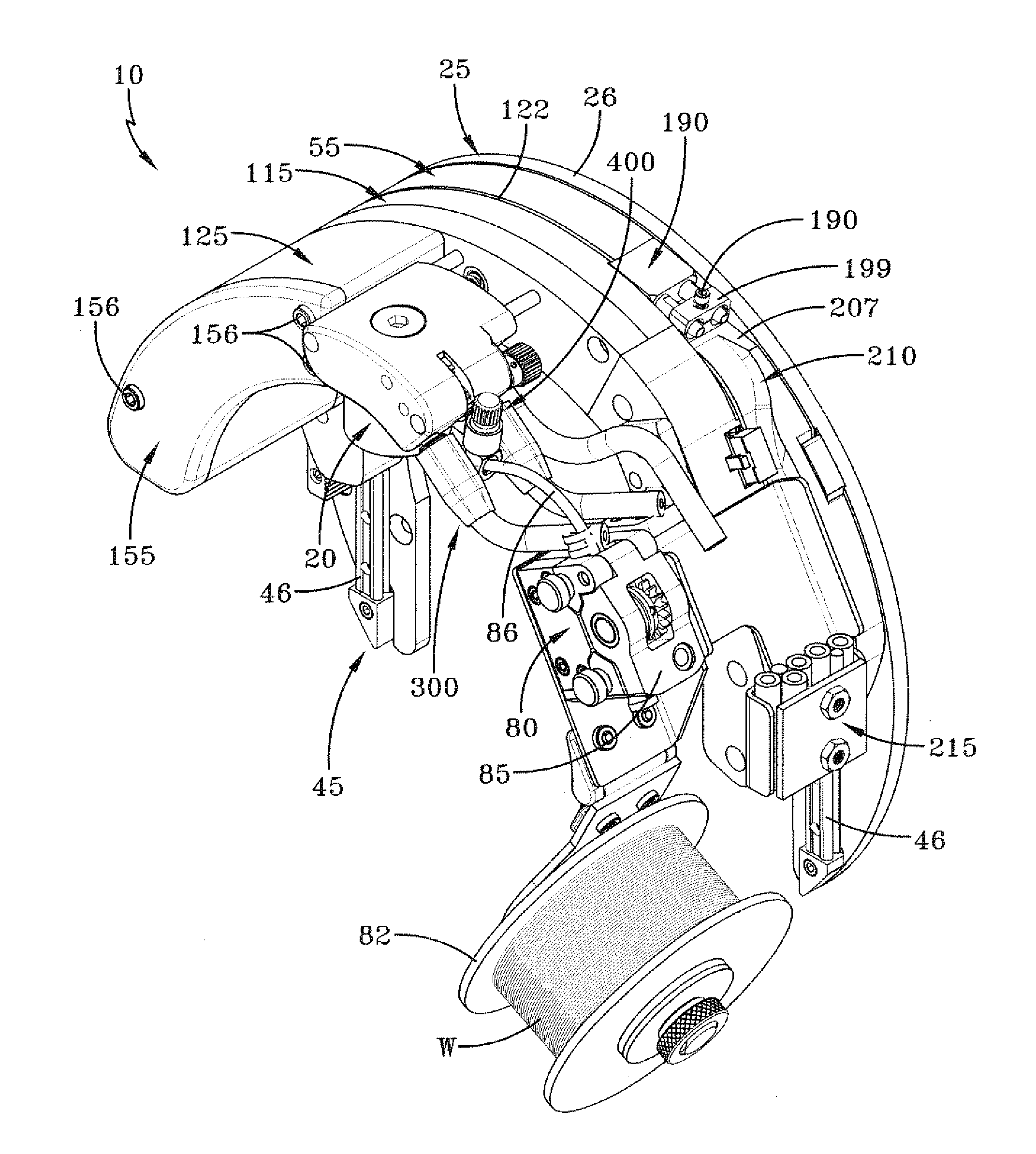
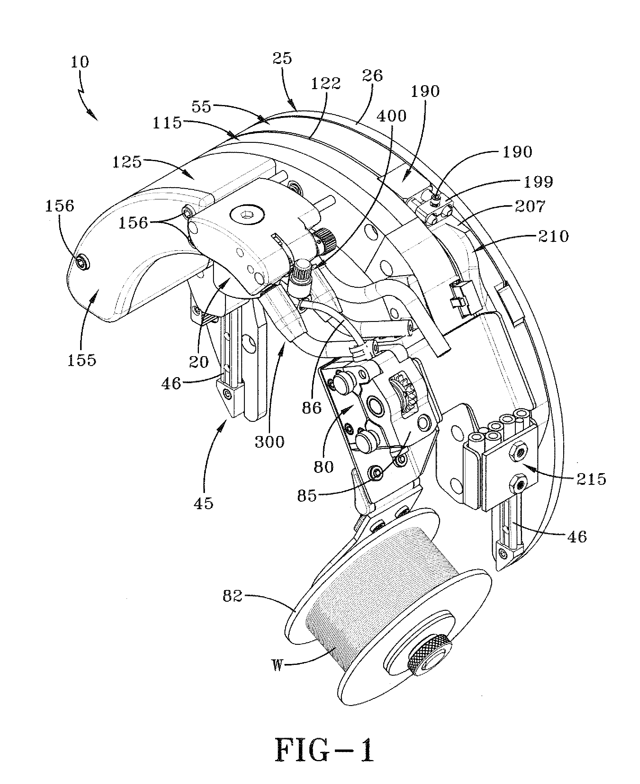
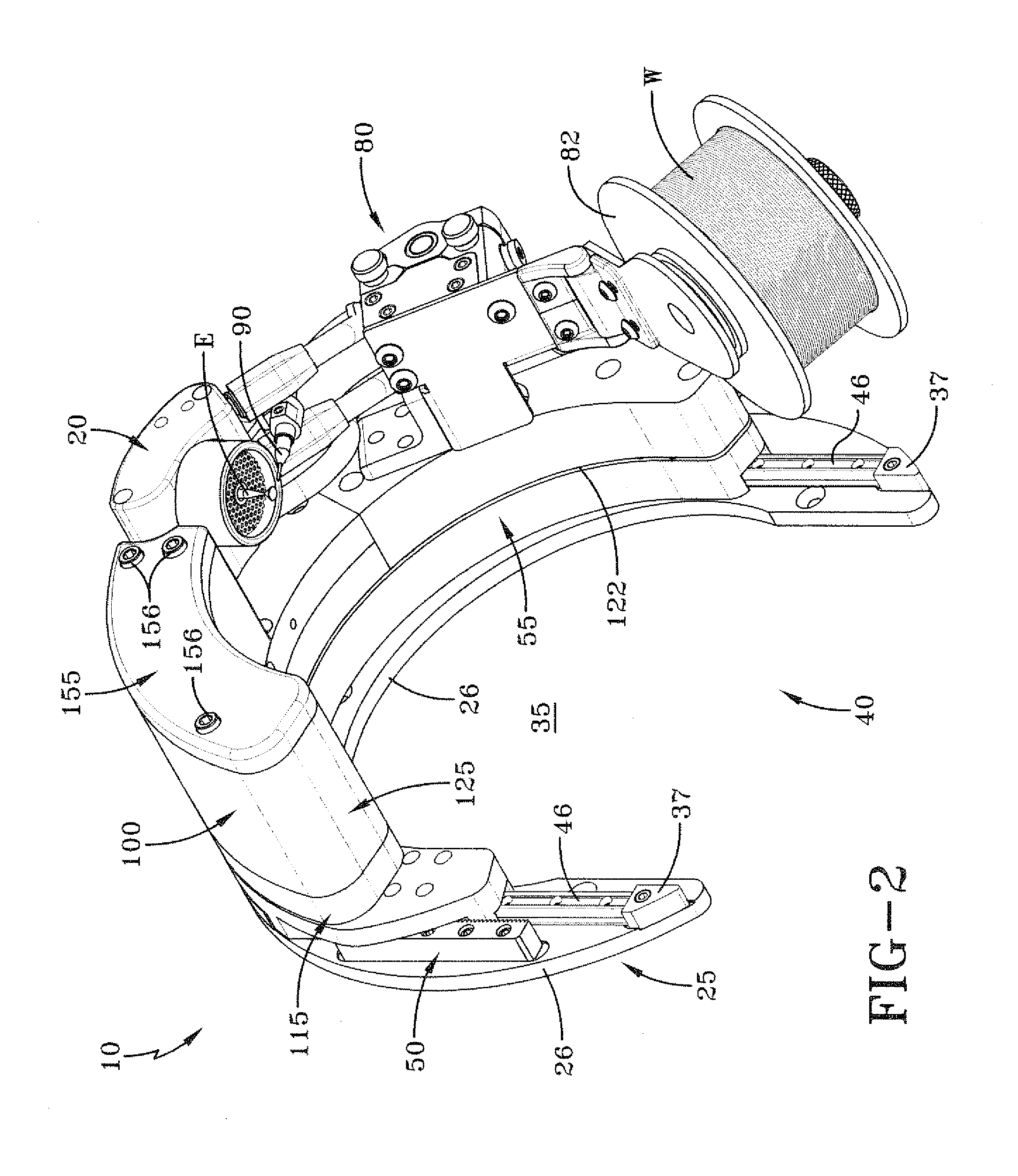
[0029]Exemplary embodiments of the invention will now be described below by reference to the attached figures. The described exemplary embodiments and embodiments shown in the figures are intended to assist the reader in the understanding of the invention, and are not intended to limit the scope of the invention in anyway. “Welding” or “weld” as used herein including any other formatives of these words will refer to depositing of molten material through the operation of an electric arc including but not limited to submerged arc, GMAW, MAG, MIG, and TIG welding.

[0030]The welding system according to the present invention is generally indicated by the number 10 in drawings. Welding system 10 includes an electrode E that is powered to create an arc between electrode E and a workpiece WP. The area to which the weld is applied includes a molten weld puddle, which may include material deposited by welding system 10 and molten metal from the workpiece WP created by arc penetration. For simp...


PUM

PropertyMeasurementUnit
Poweraaaaaaaaaa
Electrical conductoraaaaaaaaaa
Areaaaaaaaaaaa

Abstract

A torch head in a welding system for applying a weld to a workpiece, the torch head including a torch head body having a first side, a second side, an inward side and a outer side, the torch head body further including a lower surface and a top surface forming a solid; the torch body defining a slot extending from the lower surface to the top surface on the first side; an electrode assembly including an electrode mounted on the torch body, the electrode extending downward relative to the lower surface of the torch body; a wire adjustment assembly including a bracket supporting a wire guide that receives a wire from a wire supply; the bracket being attached to a rack and pinion supported within the slot, the rack being located inward of the pinion and slideable within the slot, the pinion being rotatable within the slot, and engaged with the rack to move the bracket vertically upon rotation of the pinion to adjust the vertical position of the wire.

Description

TECHNICAL FIELD[0001]Embodiments of the present invention relate to welding systems, devices, and processes. More particularly, the present invention relates to a torch head for an orbital welding system.BACKGROUND[0002]In industrial applications, welding may involve, brazing, cladding, building up, filling, hard facing, overlaying, joining, and other welding applications. For brevity sake, these operations will be referred to collectively as welding. An orbital welder may be used when welding a curved surface. The welder may be moved about the surface or the surface may be rotated while the welder remains stationary. The most common example, where orbital welding is used, is the welding of pipe. Pipe welding may include thin wall applications or deep groove geometries where the welding electrode extends into a groove formed between the two pipes being joined to lay down successive beads of weld material to fill the groove.[0003]In any welding application, in addition to rotating th...

Claims


Application Information

Patent Timeline
IPC IPC(8): B23K9/28
CPCB23K9/282B23K9/0286B23K9/167B23K37/0211B23K37/0229B23K37/0276B23K2101/06
Inventor MILLER, VICTORCOLE, STEPHENSNEAD, JAMIL
Owner LINCOLN GLOBAL INC
Why Eureka
Try Eureka