Bone mill assembly for use with cortical and cancellous bone

a technology of cortical and cancellous bone and bone mill, which is applied in the field of bone mill assembly, can solve the problems of rendering ground products useless for their intended purpose, and achieve the effects of preventing bone and particulate overheating, facilitating autoclaving and compartmentalization, and maximizing the yield of processed bon

Inactive Publication Date: 2014-09-18
RAFFERTY HLDG LLC DBA RAFFERTY MACHINE & TOOL
View PDF10 Cites 2 Cited by
  • Summary
  • Abstract
  • Description
  • Claims
  • Application Information

AI Technical Summary

Benefits of technology

[0009]Accordingly, a primary object of the present invention is to provide a new, useful and non-obvious bone mill assembly that can be easily autoclaved and compartmentalized to provide easy access for purposes of cleaning and sterilizing of the component parts; that provides a solution to the problem of multi-cycle grinding whereby processed bone yield is maximized and homogeneous particulate sizes of bone are produced; that prevents the bone and particulate from overheating; and that needs to be handled only once during the grinding process which decreases the chances for cross-contamination of the bone particulate.
[0010]The bone mill assembly of the present invention obtains these objects. It provides a drive motor with a reducer which reduces the revolutions per minute (RPM) while increasing torque to the optimum condition that is required to grind bone fragments or stock effectively and without overheating. Overheating of the bone fragments and particulate occurs with larger and faster motors, which essentially renders the ground product useless for its intended purpose. The drive motor in the assembly of the present invention grinds the product efficiently and without burning. The drive motor is connected to a non-rotating coupler and the coupler is, in turn, connected to the main drive grinding or cutting head of the mill. The assembly further includes a mill housing which consists of a manual feed chute or a pneumatic feed chute that shuttles the bone stock onto the main drive grinding or cutting head of the mill. The bone stock is ground to a smaller particle size and then shuttled by rotation onto a straight secondary blade. This chops the particle size even smaller and then is sized by an internal window sieve. If the particle size is small enough, the bone passes through the sieve into a collection pan. If the particle size is too large, it will then be rotated back up within the housing to be processed again by the main grinding or cutting head. Different sizes of the main grinding or cutting head are used for customer specific applications. The internal sieve design is unique and is the only one of its kind that also allows grounds lipids and fat to be washed out of the assembly during cleaning.

Problems solved by technology

Overheating of the bone fragments and particulate occurs with larger and faster motors, which essentially renders the ground product useless for its intended purpose.

Method used


Image

  • Bone mill assembly for use with cortical and cancellous bone
  • Bone mill assembly for use with cortical and cancellous bone
  • Bone mill assembly for use with cortical and cancellous bone

Examples


Embodiment Construction

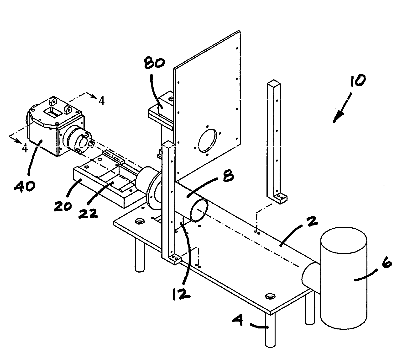
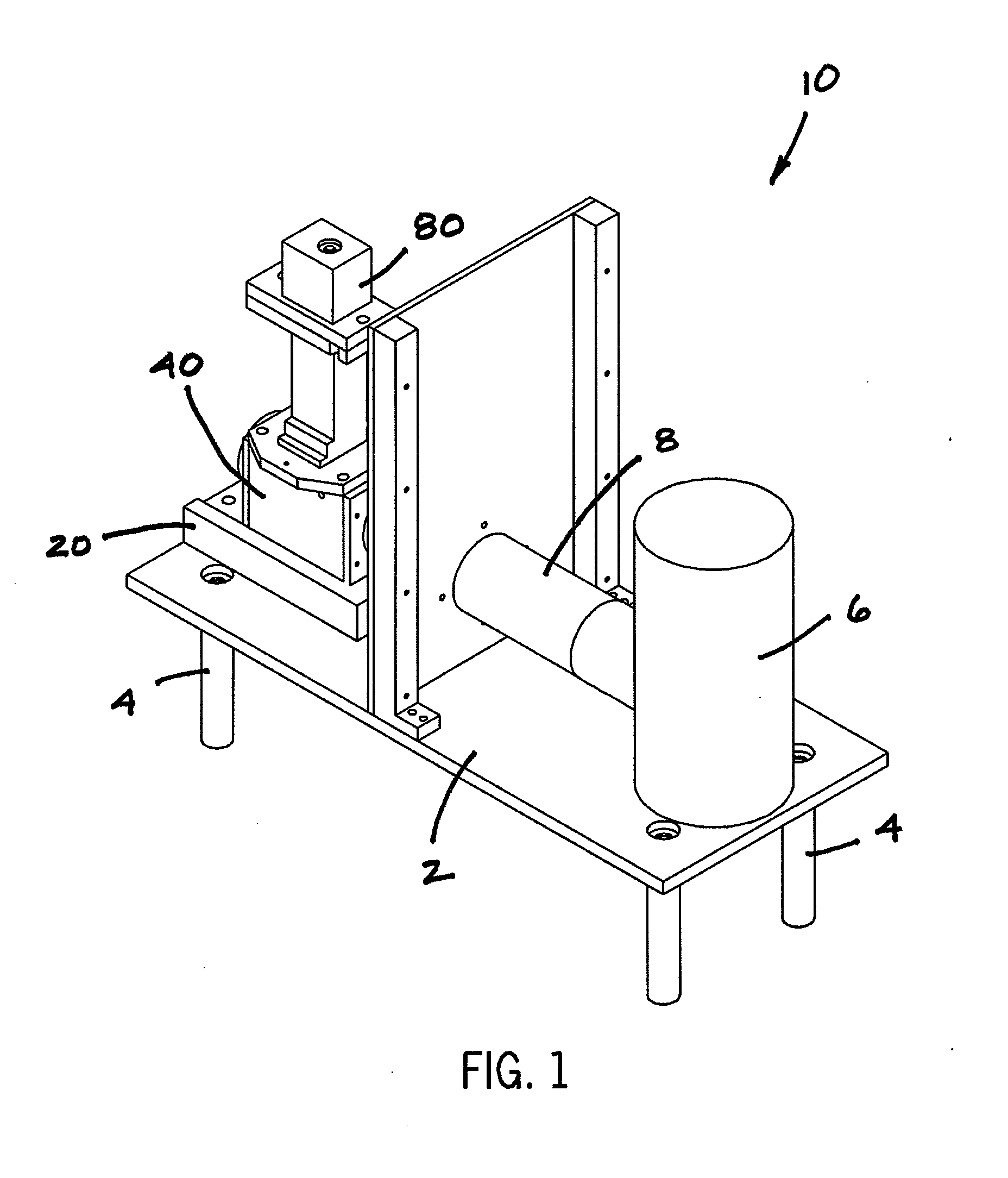
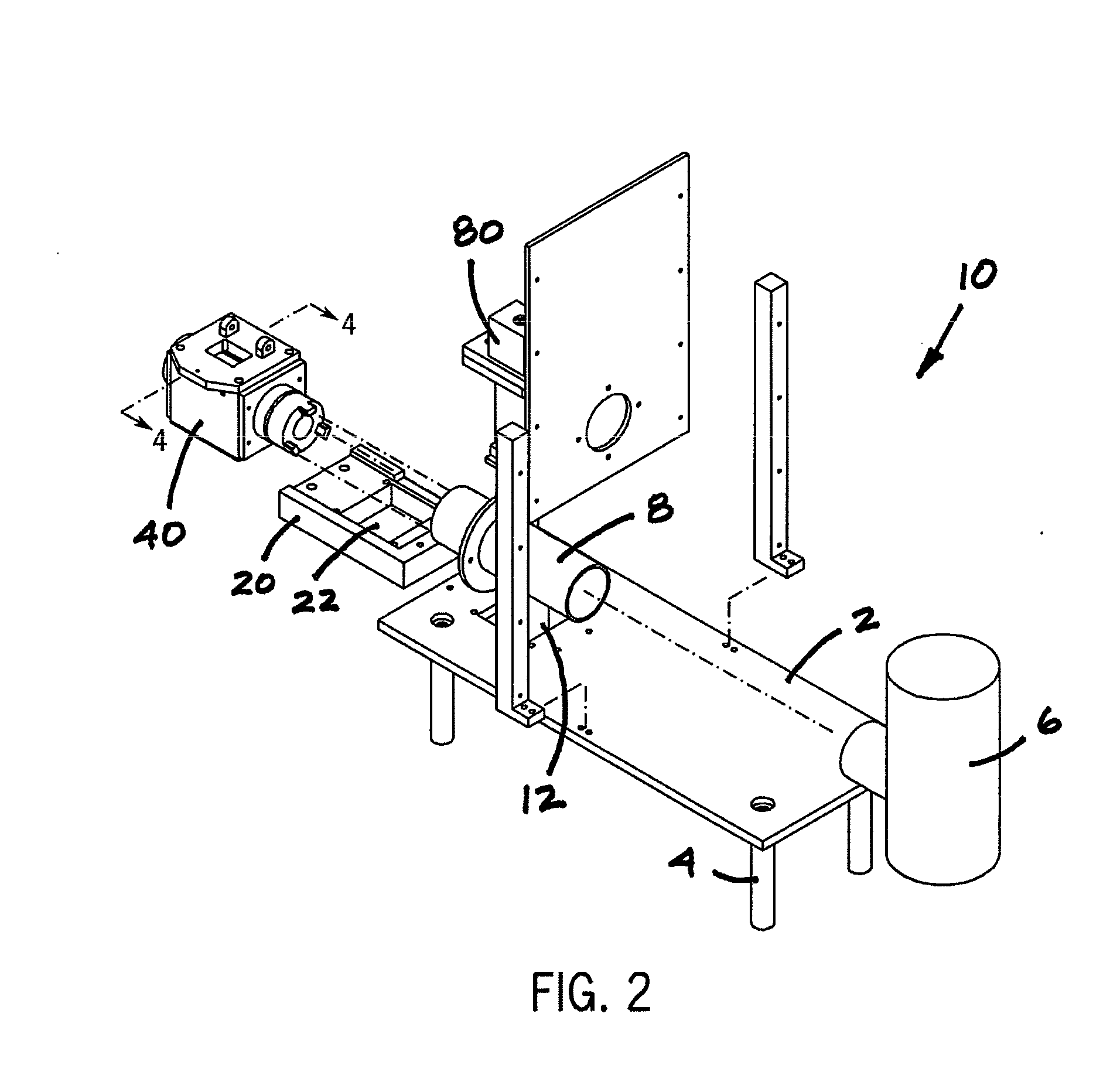
[0017]Referring now to the drawings in detail, wherein like numbered elements refer to like elements throughout, FIG. 1 illustrates the bone mill assembly, generally identified 10, which is constructed in accordance with the present invention. The bone mill assembly 10 is configured to include a working surface 2, the surface 2 being supported by a plurality of legs 4. The significance of the elevated working surface 2 is that milled bone particulate (not shown) can be collected in some sort of collection pan or container (also not shown) that can be secured beneath the surface 2. Accordingly, it is to be understood that the illustrated embodiment is not a limitation of the present invention and that the working surface 2 and legs 4 could assume most any configuration for purposes of the present invention. It is, however, preferable that the surface 2 and legs 4 be constructed of stainless steel for purposes of post-use sterilization.

[0018]A drive motor and reducer, generally and ge...


PUM


Abstract

A bone mill assembly provides a drive motor with a reducer. The drive motor is connected to a non-rotating coupler which is connected to a main drive cutting head. A mill housing consists of a manual feed chute or a pneumatic feed chute that shuttles the bone stock onto the main drive cutting head of the mill. The bone stock is ground to a smaller particle size and then shuttled by rotation onto a straight secondary blade. This chops the particle size even smaller and then is sized by an internal window sieve. If the particle size is small enough, the bone particulate passes through the sieve into a collection pan. If the particle size is too large, it will then be rotated back up within the housing to be processed again by the main cutting head. Different sizes of the main cutting head are used for customer specific applications.

Description

FIELD OF THE INVENTION[0001]The present invention generally relates to medical devices and their use. More particularly, the present invention relates to a bone mill assembly for use in a surgical, medical, or other environment where ground cortical and cancellous bone particles are needed.BACKGROUND OF THE INVENTION[0002]Ground bone particles can be used in various medical, surgical and dental procedures. Finely ground bone particles can be used for spinal fusions, to repair defects caused by trauma, transplant surgery, or tissue banking.[0003]In the prior art, it is well known that a surgeon, for example, may remove a portion of bone from a patient, grind the portion into fairly homogenous particles using a hand-powered rasp, and then use the bone particles to patch and repair another area of bone, such as on the patient's spinal cord or skull.[0004]The grinding of bone using a hand-powered rasp is a relatively long and strenuous process, however, and one that tends to yield mixed...

Claims


Application Information

Patent Timeline
Patent Type & Authority Applications(United States)
IPC IPC(8): B02C23/16
CPCB02C23/16B02C18/14B02C18/16B02C19/0056B02C2018/188B02C2023/165
Inventor TOMLINSON, CONWAYROBINSON, JAMES
Owner RAFFERTY HLDG LLC DBA RAFFERTY MACHINE & TOOL
Why Eureka
Try Eureka