Endoscopic device with temperature based light source control

a technology of light source control and endoscopic device, which is applied in the field of endoscopic system, can solve the problems of excessive heating of semi-rigid and flexible endoscopic device, hot during use, and distracting the operator's attention from the medical procedure, so as to reduce the likelihood of patient burns and enhance safety

Inactive Publication Date: 2008-03-06
KARL STORZ ENDOVISION INC
View PDF12 Cites 23 Cited by
  • Summary
  • Abstract
  • Description
  • Claims
  • Application Information

AI Technical Summary

Benefits of technology

[0011]Accordingly, it is an object of the present invention to provide an endoscopic system which provides enhanced safety and reduces the likelihood of patient burns.
[0012]Another object of the present invention is to provide an endoscopic system having the above characteristics and which ensures that the temperature of an endoscopic device does not exceed a threshold temperature.
[0015]Yet a further object of the present invention is to provide an endoscopic system having the above characteristics and which employs temperature sensors that do not create voltage, and therefore do not compromise patient safety.
[0016]Still yet a further object of the present invention is to provide an endoscopic system having the above characteristics and which employs temperature sensors that do not require a mechanical wire connection, so that the endoscopic device may be readily autoclaved.

Problems solved by technology

A disadvantage of traditional endoscopic devices, whether conventional or electronic, is that they can become hot during use due to the high amount of light energy passing therethrough required to illuminate the area or cavity of observation.
This is especially true in the case of metal bodied, rigid endoscopes, but excessive heating can also occur in connection with semi-rigid and flexible endoscopic devices.
This technique, however, is problematic in that it distracts the operator's attention away from the medical procedure being performed.
Moreover, it is difficult to know precisely how much the intensity of the light should be varied in order to ensure that the threshold temperature is not exceeded, while at the same time ensuring that the intensity of the illumination light is maintained as high as is safely possible to enhance viewing.
One of the reasons for this may be that traditional types of temperature sensors are not appropriate for use in measuring temperature along an endoscopic device.
For example, while the application of thermocouples for measuring temperature is well known, such devices could not be effectively used in connection with measuring temperature along an endoscope for a number of reasons.
More specifically, thermocouples are typically relatively large with respect to the available volume within the endoscopic device, thermocouples are electrical devices that create voltage, and therefore may compromise patient safety, and thermocouples require a mechanical wire connection, which may be problematic since endoscopic devices typically must be autoclaved.

Method used


Image

  • Endoscopic device with temperature based light source control
  • Endoscopic device with temperature based light source control
  • Endoscopic device with temperature based light source control

Examples


Embodiment Construction

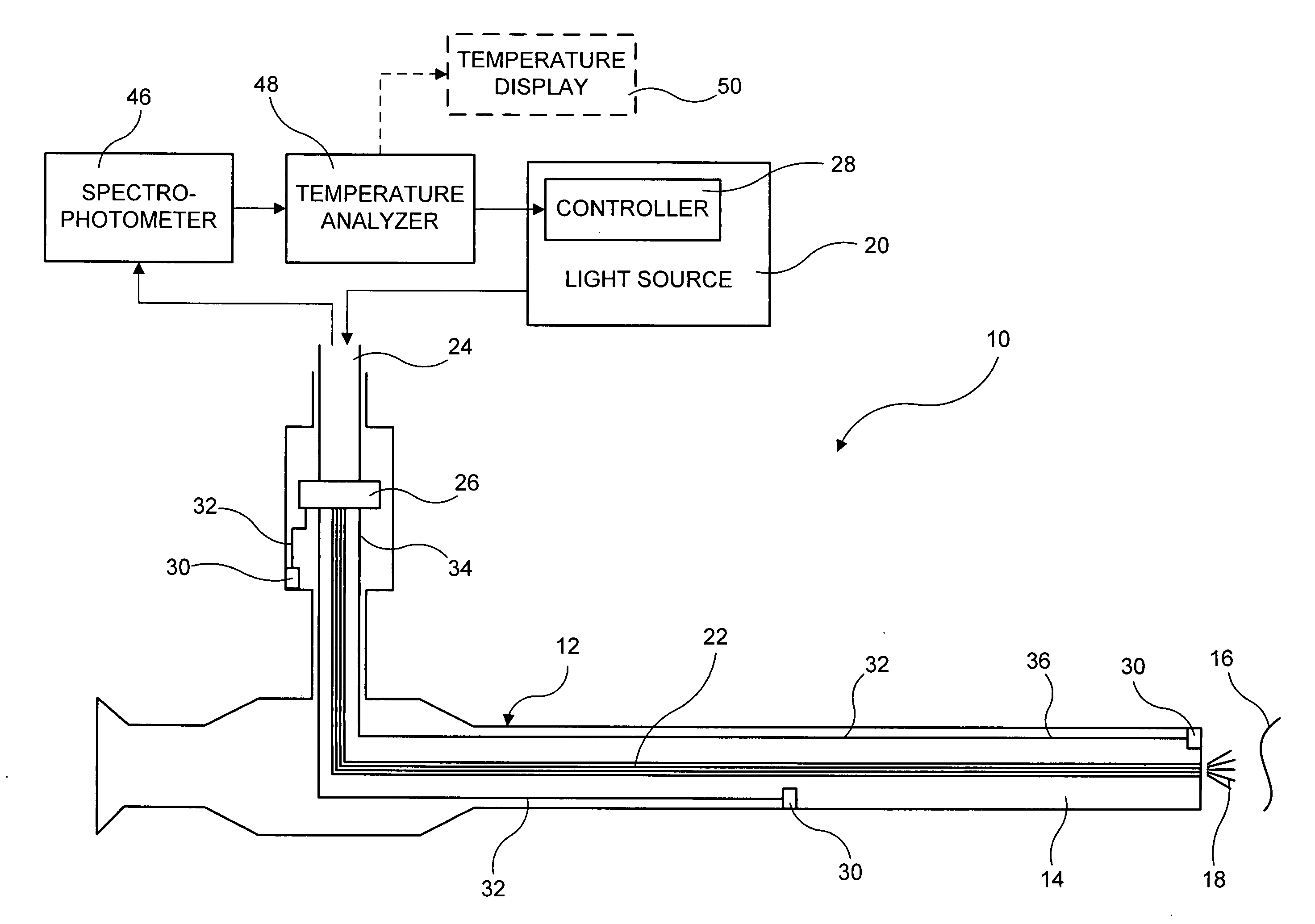
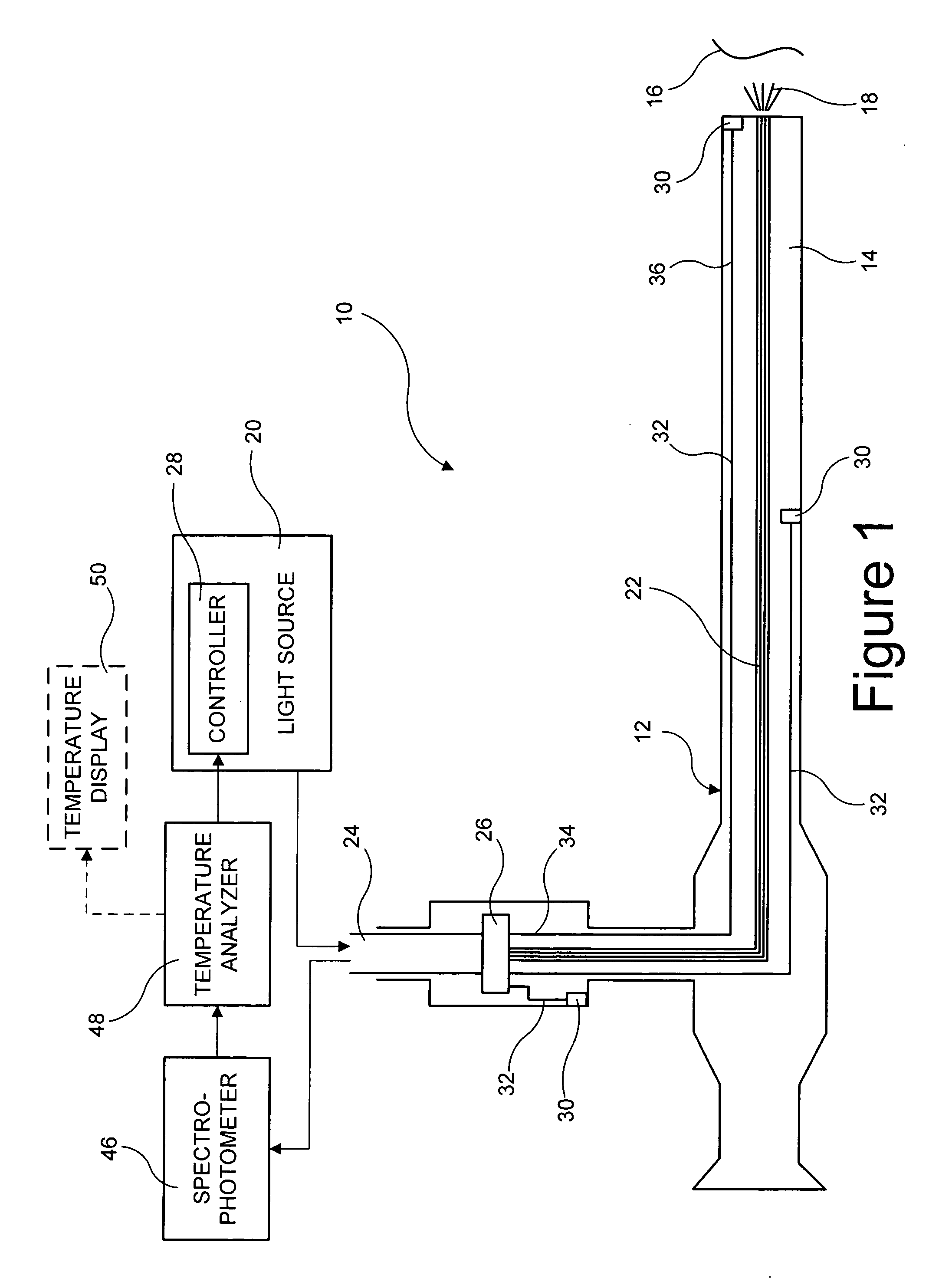
[0034]Referring first to FIG. 1, an endoscopic system 10 in accordance with an exemplary embodiment of the present invention is shown. Endoscopic system 10 includes an endoscopic device 12, which may comprise a conventional endoscope with an eyepiece and an optical transmission means, such as a lens system or a fiber optic system, an electronic endoscope having a distally disposed imaging unit or camera head mounted at the proximal end to produce video images, or some other type of image viewing system. However, because numerous types of image capture / viewing systems are well known in the art, and because the present invention is concerned with the illumination system, rather than the image capture / viewing system, the numerous image capture / viewing systems in connection with which the present invention may be used are not described herein and the elements thereof are not shown in the Figures for the sake of clarity. Moreover, it should be noted that the present invention may be used...


PUM


Abstract

An endoscopic system includes an endoscopic device having a light guide passing therethrough to a distal end thereof, a light source in communication with the endoscopic device, the light source transmitting illumination light to the light guide, a light source controller in communication with the light source, the light source controller controlling an intensity of the illumination light transmitted to the light guide, and at least one temperature sensor, at least a portion of which is carried by the endoscopic device. The temperature sensor senses a temperature of at least a portion of the endoscopic device and produces a signal indicative of the sensed temperature, the signal being transmitted to the light source controller. The light source controller varies the intensity of the illumination light transmitted to the light guide based at least in part upon the signal indicative of the sensed temperature.

Description

FIELD OF THE INVENTION [0001]This present invention relates generally to an endoscopic system including a light source for supplying illumination light to an endoscopic device, and more particularly to such an endoscopic system in which the light source is automatically controlled based upon temperature related feedback.BACKGROUND OF THE INVENTION [0002]The imaging of body surfaces through endoscopes is well known within the medical and veterinary fields. Typically, this involves inserting an endoscope into a body cavity and directing an intense light source output through the endoscope to illuminate body tissue. Light reflected by the body tissue then is guided along an optical path either to an eyepiece for direct viewing of the tissue (in the case of a conventional endoscope) or to an image sensor to generate a video image of the tissue (in the case of an electronic endoscope).[0003]The illumination light emanating from the light source is propagated to the distal part of the ins...

Claims


Application Information

Patent Timeline
Patent Type & Authority Applications(United States)
IPC IPC(8): A61B1/06A61B1/00
CPCA61B1/00055A61B1/0017A61B1/0638A61B1/128A61B2562/0271A61B2562/043A61B1/07A61B1/0655
Inventor LANDRY, DANA J.
Owner KARL STORZ ENDOVISION INC
Why Eureka
Try Eureka