Controlled Electronic System Power Dissipation via an Auxiliary-Power Dissipation Circuit

Inactive Publication Date: 2014-09-18
SIGNIFY HLDG BV
View PDF8 Cites 14 Cited by
  • Summary
  • Abstract
  • Description
  • Claims
  • Application Information

AI Technical Summary

Benefits of technology

The invention is an apparatus and method for controlling the transfer of excess energy from a power supply to an auxiliary power dissipation circuit for use by a dimmer or other load. This helps to ensure the dimmer operates properly and safely with the load.

Problems solved by technology

All switching power converters have some inherent power losses due to, for example, non-ideal component characteristics.
Premature disconnects can cause problems with the lighting system, such as flicker and instability.
However, circuits are generally designed to minimize inherent power losses, and these inherent power losses are often negligible and, thus, insufficient to dissipate enough power to compensate for the difference between the POWER IN power and the POWER OUT+PINH power at some POWER OUT levels.

Method used


Image

  • Controlled Electronic System Power Dissipation via an Auxiliary-Power Dissipation Circuit
  • Controlled Electronic System Power Dissipation via an Auxiliary-Power Dissipation Circuit
  • Controlled Electronic System Power Dissipation via an Auxiliary-Power Dissipation Circuit

Examples


Embodiment Construction

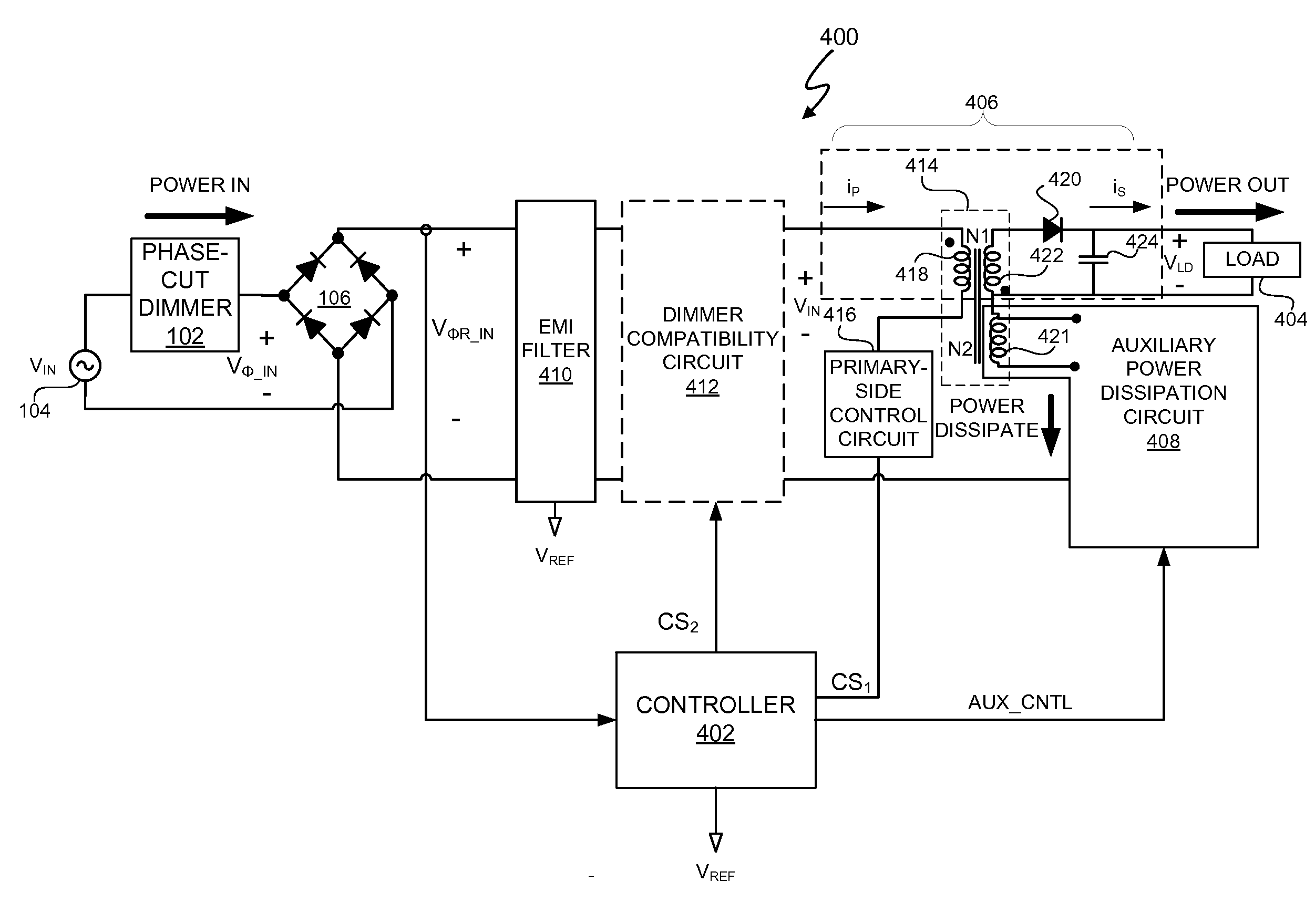
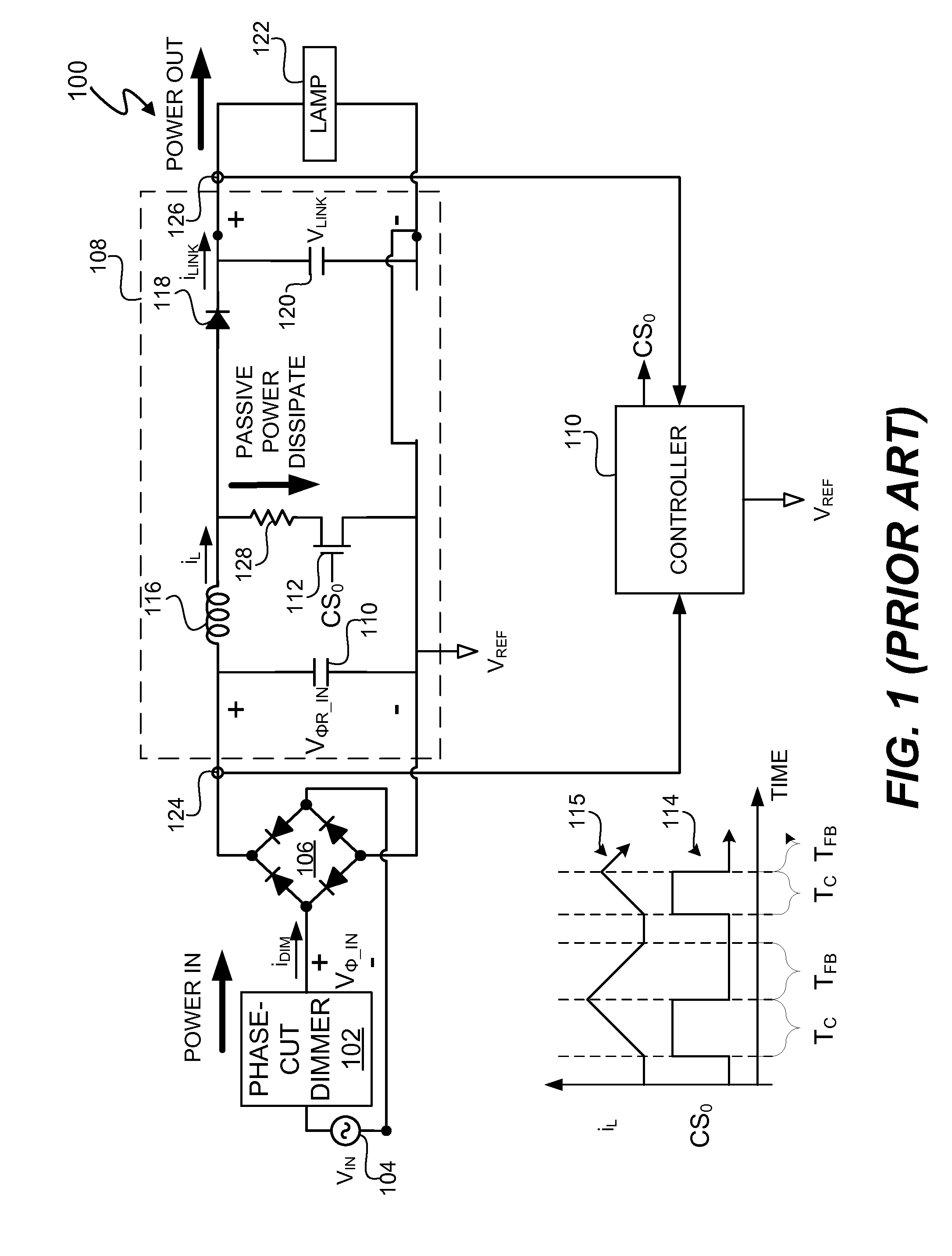
[0028]An electronic system and method include a controller to actively control transfer of excess energy to an auxiliary transformer winding of an auxiliary power dissipation circuit. The “auxiliary transformer winding” is referred to herein as an “auxiliary-winding.” The excess energy is a transfer of energy from a primary winding of a switching power converter to the auxiliary-winding of the auxiliary power dissipation circuit. In at least one embodiment, the electronic system is a lighting system that includes a triac-based dimmer. The excess energy is energy drawn through the primary-side winding of the switching power converter to provide operational compatibility between a dimmer through which a power supply provides energy to the switching power converter and a load to which the switching power converter provides energy. As previously described, when the lighting system includes a light source, such as one or more light emitting diodes (LEDs), that uses less power than an inc...


PUM


Abstract

An electronic system and method include a controller to actively control transfer of excess energy to an auxiliary-winding of an auxiliary power dissipation circuit. The excess energy is a transfer of energy from a primary winding of a switching power converter to the auxiliary-winding of the auxiliary power dissipation circuit. In at least one embodiment, the electronic system is a lighting system that includes a triac-based dimmer. The excess energy is energy drawn through the primary-side winding of the switching power converter to provide operational compatibility between a dimmer through which a power supply provides energy to the switching power converter and a load to which the switching power converter provides energy.

Description

CROSS-REFERENCE TO RELATED APPLICATION[0001]This application claims the benefit under 35 U.S.C. §119(e) and 37 C.F.R. §1.78 of U.S. Provisional Application No. 61 / 782,253, filed Mar. 14, 2013, which is incorporated by reference in its entirety.BACKGROUND OF THE INVENTION[0002]1. Field of the Invention[0003]The present invention relates in general to the field of electronics, and more specifically to a system and method of controlling power dissipation via an auxiliary power dissipation circuit of an electronic system, such as a lighting system.[0004]2. Description of the Related Art[0005]Switching power converters convert power received from a power source, such as a voltage supply, into power suitable for a load. The power received from the voltage supply is referred to as “POWER IN”, and the power provided to the load is referred to as “POWER OUT”. All switching power converters have some inherent power losses due to, for example, non-ideal component characteristics. Such inherent...

Claims


Application Information

Patent Timeline
IPC IPC(8): H05B33/08H05B44/00
CPCH05B33/0809H05B45/14H05B45/3575Y02B20/30H05B45/385
Inventor MELANSON, JOHN L.DRAKSHAPALLI, PRASHANTHMARU, SIDDHARTHSINGH, RAHUL
Owner SIGNIFY HLDG BV
Why Eureka
Try Eureka