Liquid ejecting apparatus

a technology of liquid ejecting apparatus and ejector, which is applied in printing and other directions, can solve the problems of ink-droplet discharging failure, ink-droplet discharging, and inability to discharge in the discharge direction, so as to suppress the discharging failure, prevent the wiper from wearing out, and high density

Active Publication Date: 2014-09-18
SEIKO EPSON CORP
View PDF2 Cites 10 Cited by
  • Summary
  • Abstract
  • Description
  • Claims
  • Application Information

AI Technical Summary

Benefits of technology

[0016]In this case, the wiper moves away from the protection member and lands in the portion between the nozzle openings on the nozzle plate and the end portion of the nozzle plate, which is located on the opposite side in the sweeping direction. Therefore, it is possible to prevent the wiper from coming into contact with an end surface of the nozzle plate, which is located on the opposite side in the sweeping direction. Thus, it is possible to prevent the liquid repellent film formed on the liquid ejection surface from being separated and to prevent the wiper from wearing out. In addition, the wiper lands on the liquid ejection surface and reliably sweeps the nozzle openings and the vicinities of the nozzle openings, and thus it is possible to suppress the discharging failure owing to unwiped remnants around the nozzle openings.
[0017]It is preferable that the nozzle plate be constituted by a silicon single crystal substrate. In this case, it is possible to perform processing with high density and high accuracy and to prevent the wiper from being damaged by shock caused when the wiper comes into contact with the nozzle plate.
[0018]It is preferable that the liquid ejecting head move, relative to the wiper, in a second direction perpendicular to a first direction which is an alignment direction of the nozzle openings through which the same kind of liquid is discharged. In this case, the liquid ejecting head is reduced in size, and thus it is possible to achieve a compact liquid ejecting apparatus.

Problems solved by technology

Thus, ink adhering to a vicinity of the nozzle opening which is formed on a liquid ejection surface and through which the ink droplets are ejected, or the solidified ink adhering to the vicinity of the nozzle opening causes a problem, such as an unstable ink-droplet discharge direction and discharging failure, for example, ink-droplet discharging failure.
Furthermore, there is a problem in that, even in a condition where the liquid ejection surface is wiped by the wiper blade, the ejection receiving medium is stained with ink, fluff, dust, or paper dust which adheres to a surface of a protection member, such as cover head, provided on the liquid ejection surface side, when the ejection receiving medium or the like comes into contact with the protection member.
However, there is a problem in that, in a case where a wiper comes into contact with an end portion of a nozzle plate when the wiper, such as a wiper blade, sweeps the liquid ejection surface, a liquid repellent film formed on a surface of the nozzle plate is likely to be separated from the end portion as a starting point.
In addition, there is a problem in that a lifespan of the wiper is shortened because the wiper is cut by a corner portion of the nozzle plate when the wiper comes into contact with the end portion of the nozzle plate.
Furthermore, there is a problem in that, in a case where the nozzle plate is constituted by a silicon single crystal substrate, the nozzle plate is likely to be damaged when the wiper comes into contact with the end portion of the nozzle plate.
Incidentally, in a case where the wiper skips over the nozzle opening and lands on the liquid ejection surface, unwiped remnants are left around the nozzle opening, and thus it is difficult to suppress discharging failure.
These problems are not limited to an ink jet type recording apparatus but are common to a liquid ejecting apparatus in which liquid other than ink is ejected.

Method used


Image

  • Liquid ejecting apparatus
  • Liquid ejecting apparatus
  • Liquid ejecting apparatus

Examples


embodiment 1

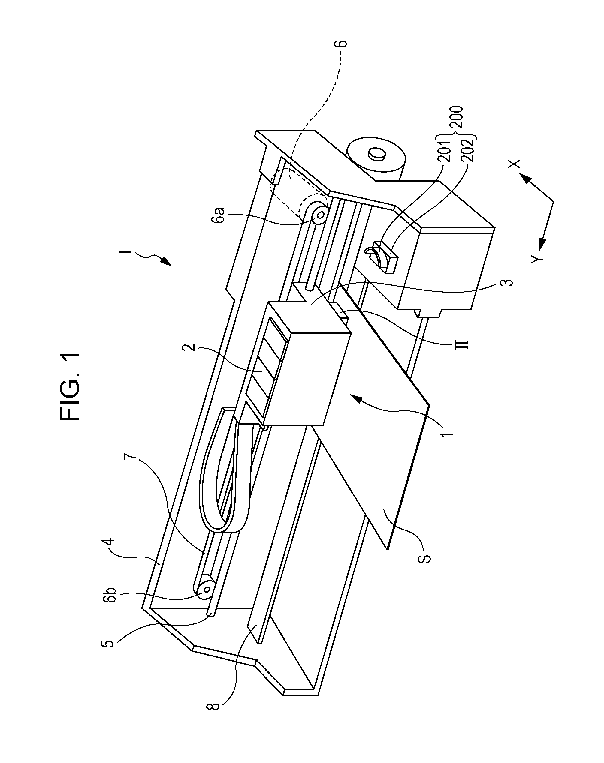
[0028]FIG. 1 is a perspective view illustrating the schematic configuration of an ink jet type recording apparatus as an example of a liquid ejecting apparatus according to Embodiment 1 of the invention.

[0029]An ink jet type recording apparatus I which is a liquid ejecting apparatus in Embodiment 1 is equipped with an ink jet type recording head unit 1 (also referred to as a head unit 1, hereinafter) including a plurality of ink jet type recording heads II (also referred to as a recording head II, hereinafter), as illustrated in FIG. 1. An ink cartridge 2 constituting an ink feeding unit is detachably installed in the head unit 1. A carriage 3 on which the head unit 1 is mounted is axially movably mounted on a carriage shaft 5 which is installed in an apparatus main body 4. This head unit 1 discharges a black-ink composition and a color-ink composition.

[0030]In addition, a driving motor 6 is provided in a vicinity of one end portion of the carriage shaft 5, and a first pulley 6a hav...


PUM


Abstract

Provided is a liquid ejecting apparatus including a liquid ejecting head that ejects liquid through nozzle openings, and a wiper that sweeps a liquid ejection surface side of the liquid ejecting head, in which the liquid ejecting head includes a nozzle plate having the liquid ejection surface and a protection member that protrudes further on a liquid discharging side than the nozzle plate, and the wiper sweeps a surface of the protection member, which is an exterior surface of the protection member intended to be swept, toward the nozzle plate side, and then the wiper sweeps the liquid ejection surface so that the wiper moves away from the surface of the protection member and comes into contact with a portion between the nozzle openings on the nozzle plate and an end portion of the nozzle plate, which is located on an opposite side in a sweeping direction.

Description

BACKGROUND[0001]1. Technical Field[0002]The present invention relates to a liquid ejecting apparatus equipped with a liquid ejecting head which ejects liquid through nozzle openings and particularly relates to an ink jet type recording apparatus equipped with an ink jet type recording head which ejects ink as liquid.[0003]2. Related Art[0004]An ink jet type recording apparatus in which ink as liquid is ejected to perform printing on a recording medium (an ejection receiving medium), such as a paper sheet and a recording sheet, has been known as a liquid ejecting apparatus in which liquid is ejected onto an ejection receiving medium, for example.[0005]In the case of an ink jet type recording head mounted on the ink jet type recording apparatus described above, ink droplets are discharged, through nozzle openings, onto the ejection receiving medium. Thus, ink adhering to a vicinity of the nozzle opening which is formed on a liquid ejection surface and through which the ink droplets ar...

Claims


Application Information

Patent Timeline
Patent Type & Authority Applications(United States)
IPC IPC(8): B41J2/165
CPCB41J2/16535B41J2/16505B41J2/16538B41J2/14233B41J2/1433B41J2002/14362B41J2002/14419B41J2002/14491
Inventor NAKAO, HAJIMEENOMOTO, KATSUMIWATANABE, SHUNSUKE
Owner SEIKO EPSON CORP
Why Eureka
Try Eureka