Uneven density is caused by various elements, such as uneven charging of the image baring member due to non-uniform charging, uneven
exposure by the
exposure device, uneven rotation or uneven sensitivity of the image bearing member such as a photosensitive member, uneven resistance of a developer bearing member such as a development roller, uneven charging of toner, and uneven transfer by a transfer roller, for example.
Uneven density attributed to, among other things, the uneven rotation or uneven sensitivity of the image bearing member particularly occurs at relatively short intervals, and thus periodically occurs within a page and is easily noticeable, which is often the cause of a complaint.
The uneven rotation of the image baring member, therefore, changes a development gap between the image baring member and the developer bearing member, resulting in a change in the
electric field and thus a change in image density.
As a result, the
electric field fluctuates and hence the density changes, resulting in uneven density.
Reducing the changes in the sensitivity of the image bearing member by using a highly accurate manufacturing method leads to a higher cost which complicates efforts to reduce the manufacturing cost.
If a parameter such as the development bias is controlled to correct uneven density in the shadow portion, therefore, the effect of the control is not achieved in the
halftone or highlighted image portion, and uneven density is increased.
This is because even when the phase of the rotators is detected, if the
layout distance between the
operating point of the control and the toner
image detector is not an integral multiple of the rotational period of the rotators, it is difficult to apply accurately the correction data in such a manner as to suppress the uneven density.
Even when the
time information is obtained, in reality, it is difficult to apply accurately the correction data in such a manner as to suppress the uneven density.
As a result, desirable correction of the uneven density is not performed using the correction data.
The difference between a design value of the
layout distance and the actual
layout distance causes difficulty in correction of the uneven density.
Taking the design value of the layout distance into consideration is not enough to accurately match the phase of the correction data with the phase of the uneven density.
In an actual
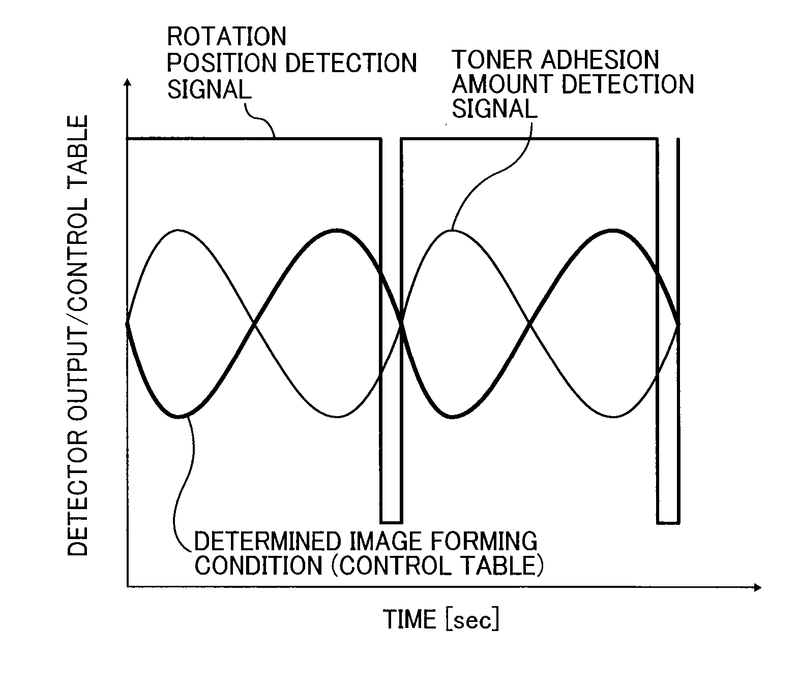
machine, due to accumulation of manufacturing tolerances and installation errors of parts, and parts variations, there is a discrepancy between the design layout distance and the target distance.
As a result, there is a discrepancy between the
time information obtained from the design value of the layout distance and the actual
time information so that the position of generation of the uneven density on the rotator and the phase of the correction data, for example, a
control table, do not correspond to each other, resulting in insufficient correction effects.
Another cause is a shift in the
control table due to a
delay in the response from a high-
voltage power pack serving as a power source to apply the development bias and the charging bias.
Because there is a
delay in the response from the high-
voltage power pack that outputs the development bias and the charging bias, the phase of the uneven density and the phase of the
control table do not coincide with each other, hence resulting in insufficient correction effects.
Furthermore, without operating the actual
machine, the substantial control
operating point of the development bias and the charging bias cannot be determined.
In other words, the substantial control
operating point of the development bias cannot be determined when using a development device using a multi-stage roller development
system and the like.
The substantial control operating point of the charging bias also cannot be determined when using a scorotron charging method using a grid
electrode.
If only taking the layout position into account, it is difficult to accurately apply the correction data for the uneven density which is made to correspond to the rotational period of the rotators in such a manner as to suppress the uneven density.

