
Glass selection for infrared lens design

a technology of infrared lens and glass selection, which is applied in the direction of optics, optical elements, instruments, etc., can solve the problems of complex reasons, difficult, if not impossible, inability to design refractive optics capable of covering such a wide range of wavelengths, etc., to achieve balanced optical design, eliminate thermal and wavelength dependence of focal length, and simplify material selection

Inactive Publication Date: 2014-09-18
SCHOTT CORP
View PDF3 Cites 8 Cited by
  • Summary
  • Abstract
  • Description
  • Claims
  • Application Information

AI Technical Summary

Benefits of technology

The invention is about a new method for designing lenses that can bring different colors into focus on the same plane, reducing chromatic aberration. This is important because lenses made from different materials have different properties that affect how they focus light. The invention provides a way to simplify the selection of materials that work together to bring about this effect. By using a consistent equation for calculating the refractive index and wavelength for different materials, the invention makes it easier to design a lens that can work in multiple wavelength bands simultaneously. This method also avoids variations in the usual behavior of the materials when changing IR bands. Overall, the invention provides a more effective way to design achromatic lenses.

Problems solved by technology

However, designing refractive optics capable of covering such a broad range of wavelengths is difficult, if not impossible, using traditional methods, which involve the use of Abbe number and partial dispersion.
The reasons for this difficulty are complex.

Method used


Image

  • Glass selection for infrared lens design
  • Glass selection for infrared lens design
  • Glass selection for infrared lens design

Examples


example 1

[0059]An achromatic doublet is prepared from a first glass element made from the glass IGX-A (K=−0.923, made by Schott Glass) and a second glass element made from the glass IGX-C (K=+2.414, made by Schott Glass). The resultant optical lens is achromatic in the wavelength ranges of 0.7 μm 1.8 μm, and 8-12 μm, and is passively athermal when mounted in a housing of CTE=29 ppm / K This value is close enough to that of aluminum (23 ppm / K) as to allow good thermal performance near room temperature with an aluminum housing. A diffractive element is used to correct for LWIR dispersion, and the refractive powers are optimized for best shortwave performance.

example 2

[0060]An achromatic doublet is prepared from a first glass element made from the glass IGX-B (K=−1.130, made by Schott Glass) and a second glass element made from an AgCl crystal (+2.274)). The resultant optical lens is achromatic in the wavelength ranges of 0.7 μm 1.8 μm, and 8-12 μm, and is passively athermal when mounted in a housing of CTE=227 ppm / K. This value is large enough to require active re-focusing or heating of the lens assembly even over a very narrow range of ambient temperatures. A diffractive element is used to correct for LWIR dispersion, and the refractive powers are optimized for best shortwave performance.

example 3

[0061]An apochromatic triplet is prepared from a first glass element made from the glass IGX-A (K=−0.817, made by Schott Glass), a second glass element made from the glass IGX-B (K=+3.434, made by Schott Glass), and a third glass element made from the glass IGX-C (K=−0.920, made by Schott Glass). The resultant optical lens is apochromatic within the wavelength range of 0.7-12 μm and is passively athermal when mounted in a housing of CTE=66 ppm / K. No diffractive element is need, but one may be used to enhance thermal or chromatic correction.


PUM


Abstract

The invention relates to process for manufacturing infrared optical lenses that will transmit in multiple infrared bands, for example, lenses with multiple optical elements such as doublet and triplet lenses (i.e., achromatic, apochromatic, and superachromatic optical elements). The lens materials are selected on the basis of dispersion ratios and / or minimum dispersions and minimum dispersion wavelengths as defined herein.

Description

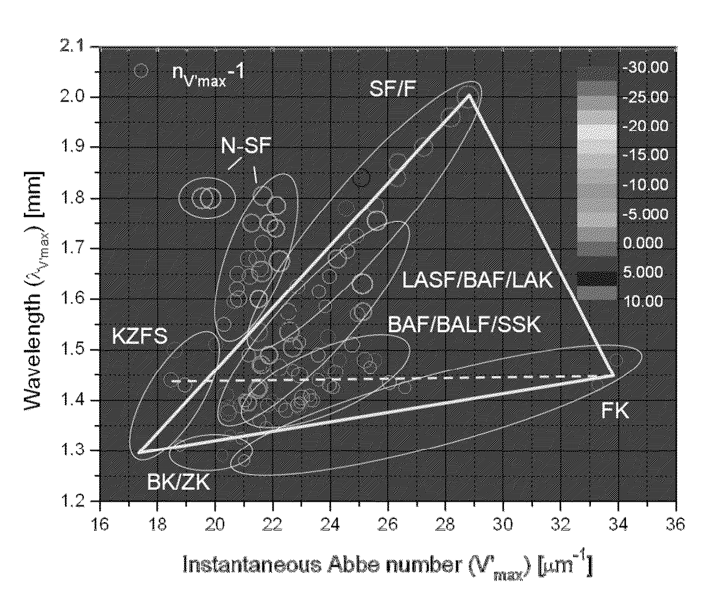
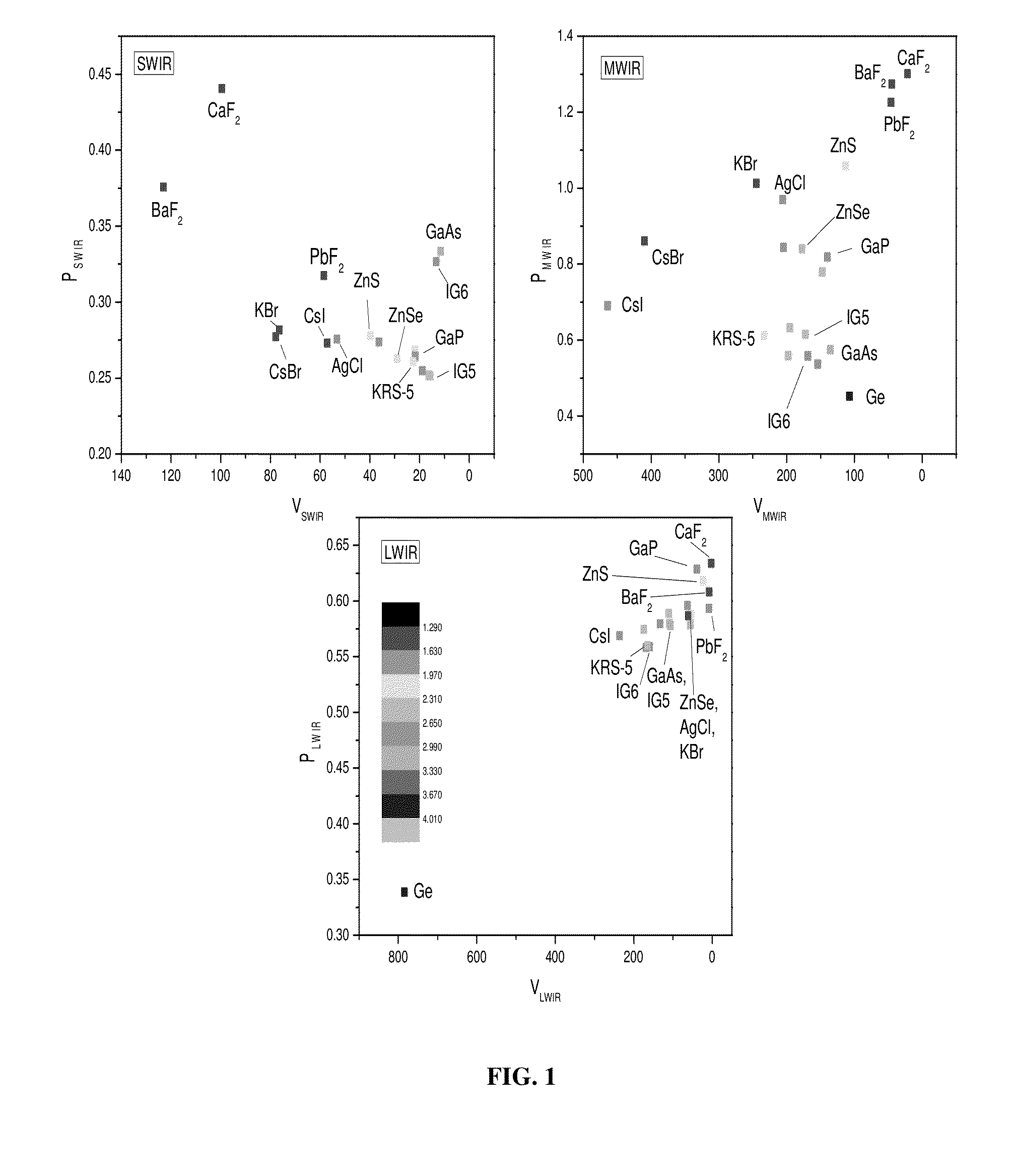
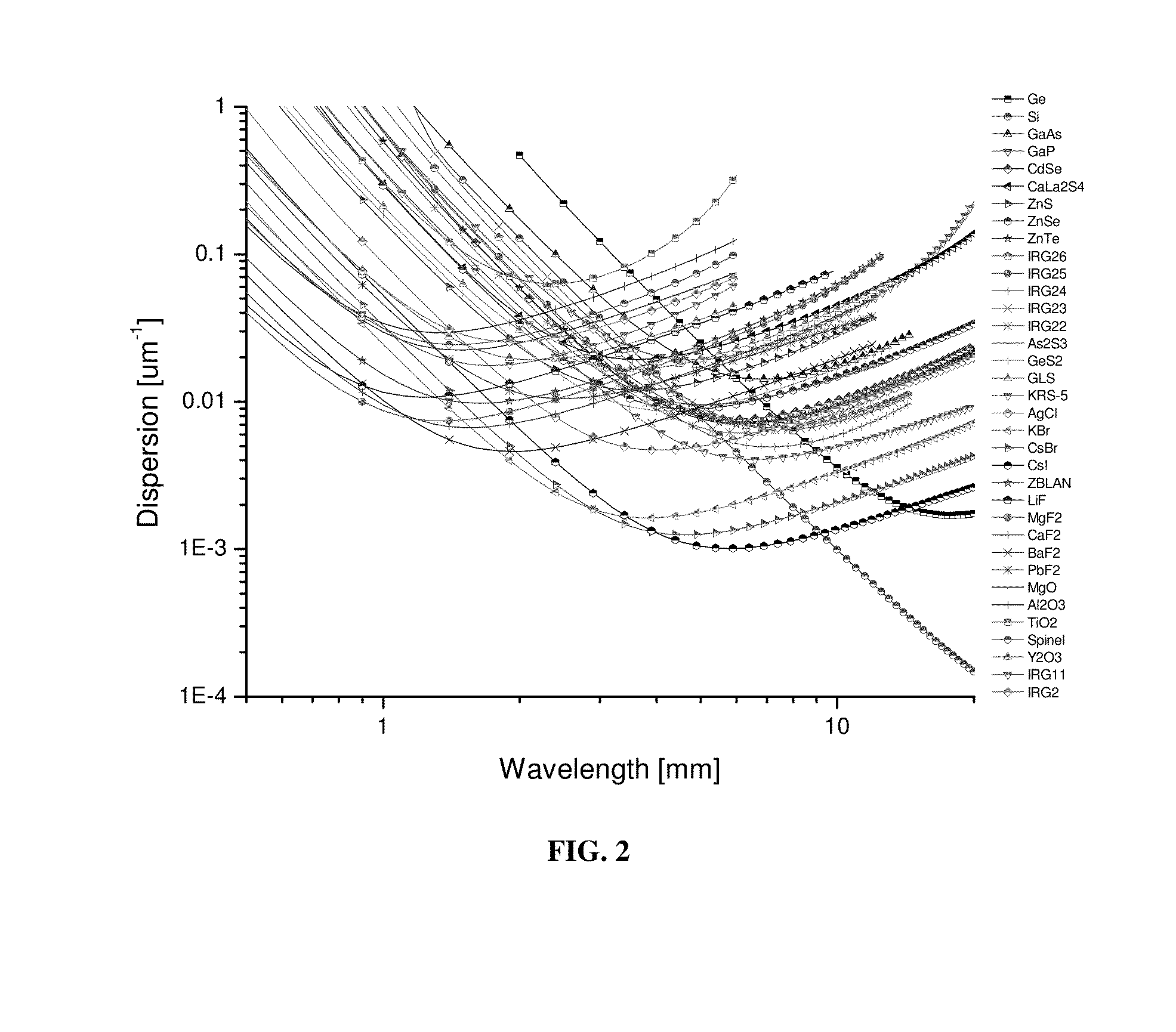
SUMMARY OF THE INVENTION[0001]The invention relates to process for manufacturing infrared optical lenses that will transmit in multiple infrared bands. For example, the invention relates to the manufacture of lenses with multiple optical elements such as doublet and triplet lenses (i.e., achromatic, apochromatic, and superachromatic optical elements) using lens materials that are selected on the basis of dispersion ratios and / or minimum dispersions and minimum dispersion wavelengths as defined herein.[0002]An achromatic lens is made by combining two different lens materials that have different dispersion properties (i.e., a positive power crown glass and a negative power flint glass). The achromatic lens functions to bring two different wavelengths both into focus on the same focal plane, thereby reducing chromatic aberration. Apochromatic lenses involve multiple materials and are designed to bring three or more wavelengths into focus in the same plane. A superachromatic lens also i...

Claims


Application Information

Patent Timeline
Patent Type & Authority Applications(United States)
IPC IPC(8): G02B13/14
CPCG02B13/14G02B1/00
Inventor CARLIE, NATHAN
Owner SCHOTT CORP
Learn More