Diode driver for battery operated laser systems

a laser system and diode driver technology, applied in the direction of electromagnetic-inducing lasers, pulse generation by energy-accumulating elements, electric pulse generator circuits, etc., can solve the problems of low efficiency, low electrical-to-optical efficiency, and the general requirement of energy for pumping such optical systems

Inactive Publication Date: 2014-09-18
RAYTHEON CO
View PDF4 Cites 19 Cited by
  • Summary
  • Abstract
  • Description
  • Claims
  • Application Information

AI Technical Summary

Benefits of technology

[0023]In some exemplary embodiments, the current driver utilizes a high-side

Problems solved by technology

The low efficiency was due mainly to the low electrical-to-optical efficiency.
However, in this configuration, the current source can only drive one load at a time and does not combine the functions of multiple diode drivers into a single diode driver.
Pumping such optical systems generally requires a substantial amount of energy.
The use of a separate diode driver for each gain stage adds volume, mass, complexity and cost to the laser system.
A drawback of these systems is that a short circuit from a diode cathode to ground will cause unlimited current to flow in the diodes until an energy storage capacitor discharges, which results in damage to the pump diodes.
In addition, in these systems, the input current is not well controlled.
Batteries used in battery-powered

Method used


Image

  • Diode driver for battery operated laser systems
  • Diode driver for battery operated laser systems
  • Diode driver for battery operated laser systems

Examples


Embodiment Construction

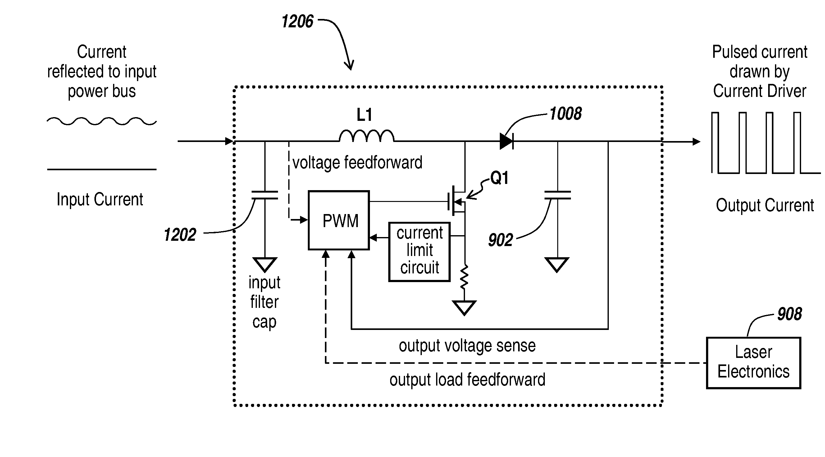
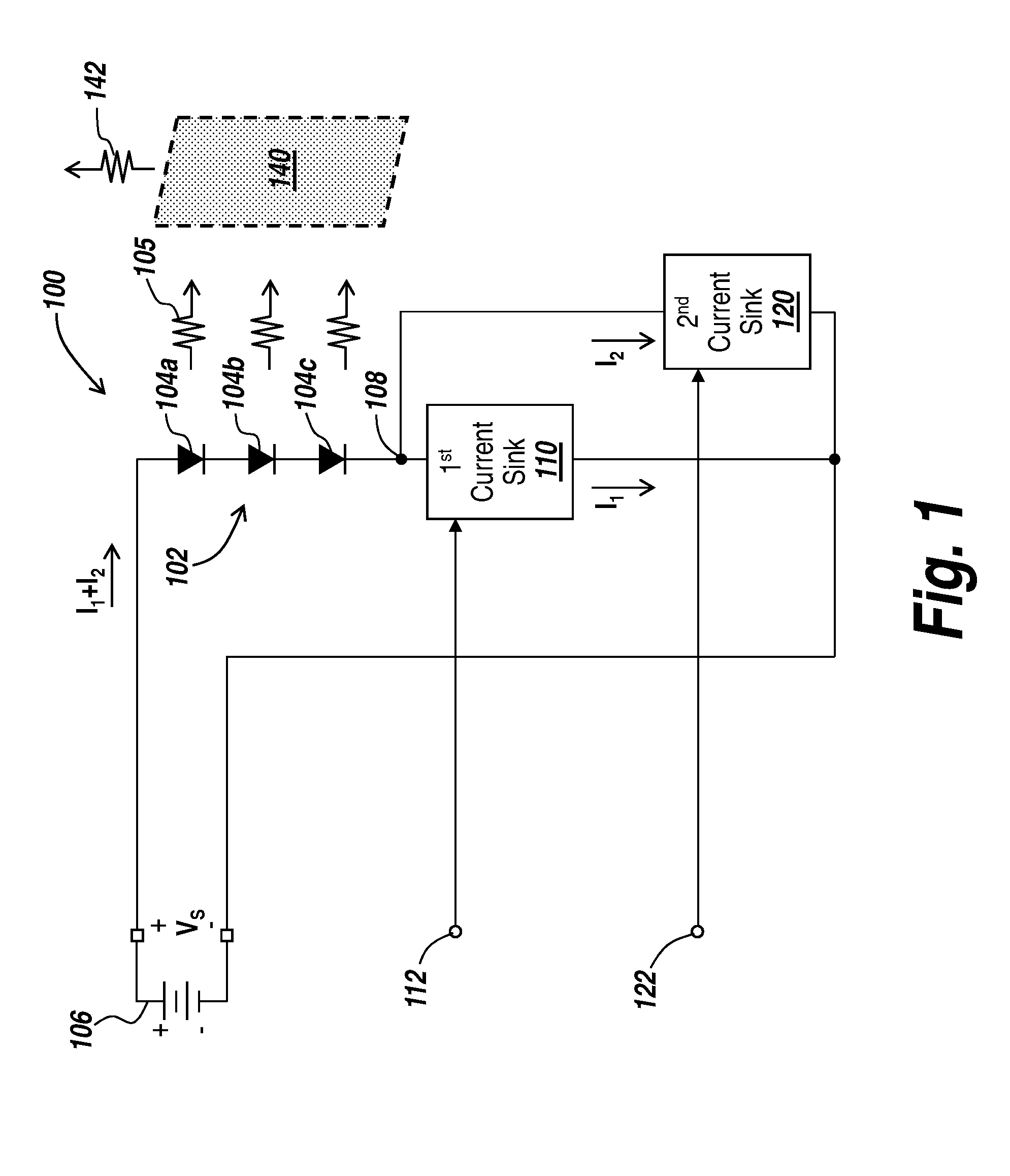
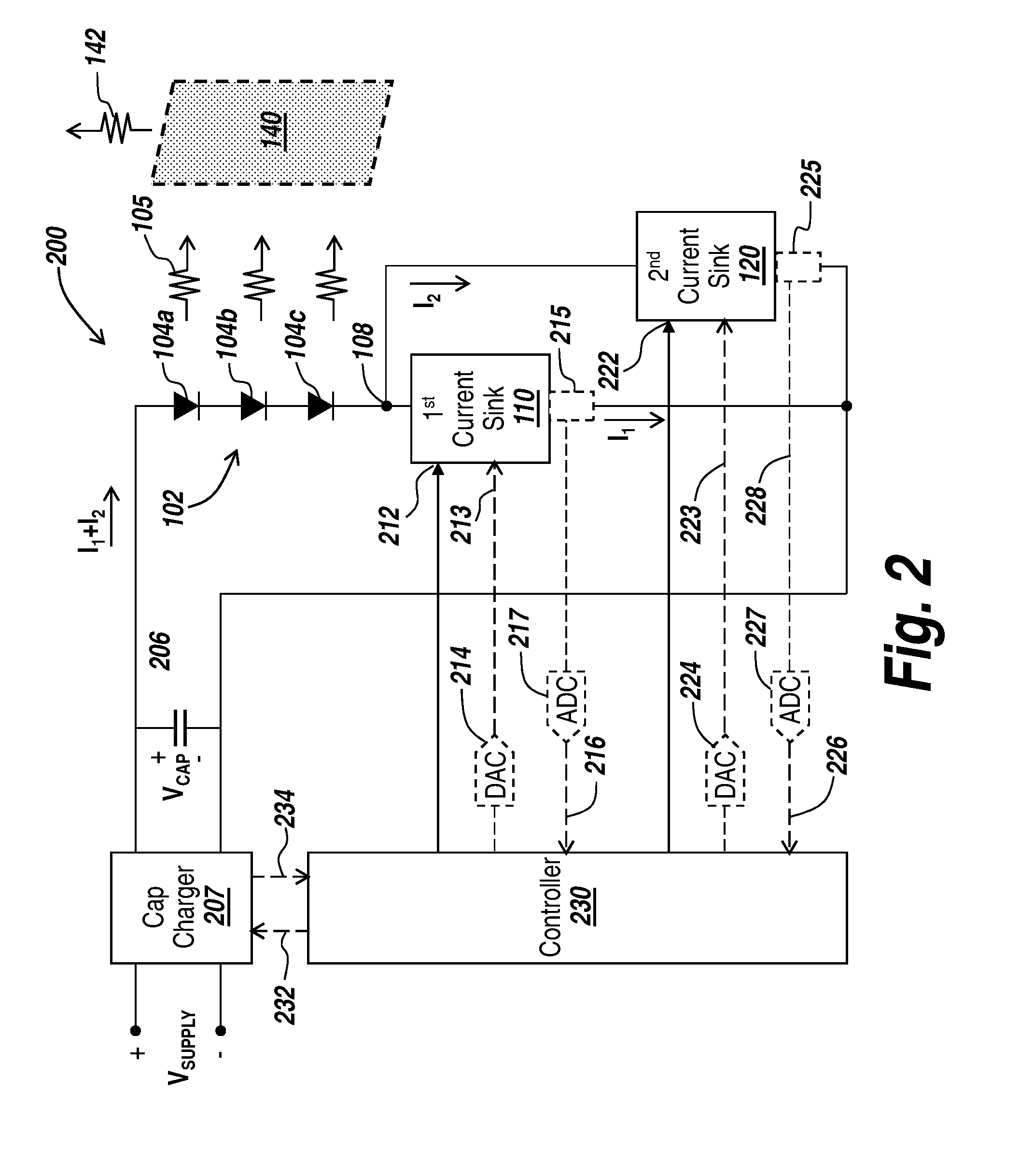
[0080]Described herein are embodiments of systems and techniques for activating light emitting devices, such as laser diodes, as may be used in connection with an optical PA or MO or PO. Multiple PAs can be used with a single MO to further enhance the output energy of a MOPA system. The light emitting devices referred to herein may be configured as a single optical emitter or an array of optical emitters arranged in a series, parallel, or parallel sets of series connected optical emitters. For the purpose of simplicity, these light emitting devices will be referred to as light emitting arrays but could, in practice, be in any of the afore mentioned arrangements.

[0081]A laser diode driver, in the most ideal form, is a constant current source, linear, noiseless, and accurate, that delivers exactly the current to the laser diode that it needs to operate for a particular application. In this configuration, one laser diode driver is used per load, such as a laser diode array that include...


PUM


Abstract

A diode driver system includes an input power source and an active line filter receiving input power from the input power source and providing a filter output power form. A current driver receives an input power form and generates a driving output signal for driving at least one diode. A capacitive energy storage device is coupled between the active line filter and the current driver, the capacitive energy storage device receiving the filter output power form from the active line filter and providing the input power form to the current driver.

Description

RELATED APPLICATIONS[0001]This application is related to U.S. application Ser. No. 13 / 215,873, filed on Aug. 23, 2011, and U.S. application Ser. No. 13 / 764,409, filed on Feb. 11, 2013, and U.S. Provisional Application No. 61 / 768,095, filed on Feb. 22, 2013 the entire contents of which applications are incorporated herein by reference.[0002]This application also claims the benefit of U.S. Provisional Application No. 61 / 792,844, filed on Mar. 15, 2013, the entire contents of which are incorporated herein by reference.BACKGROUND[0003]1. Technical Field[0004]This disclosure relates to battery powered electronics such as laser diode driving systems, and, more particularly, to systems and methods for controlling current drawn from a battery by pulsed load electronics, such as laser systems.[0005]2. Discussion of Related Art[0006]Diode pumping has become the technique of choice for use as pump sources employed in solid-state laser systems due to their relatively high electrical-to-optical ...

Claims


Application Information

Patent Timeline
IPC IPC(8): H01S3/091H05B44/00
CPCH01S3/0912H01S3/0941H01S3/1022H01S3/2308H01S5/0428H01S5/06808H01S5/4018H03K3/53H01S3/1001
Inventor ORTIZ, JOE A.
Owner RAYTHEON CO
Why Eureka
Try Eureka