Intelligent Observation And Identification Database System

a database system and intelligent technology, applied in the field of intelligent observation and identification database system, can solve the problems of inability to intelligently and/or automatically evaluate or filter information retrieved from the database in real time, delay in communication of information to an officer or guard as to the criminal history of the likely driver or registered owner of the vehicle, and failure to use optical input devices

Active Publication Date: 2014-09-18
FEDERAL LAW ENFORCEMENT DEV SERVICES
View PDF7 Cites 97 Cited by
  • Summary
  • Abstract
  • Description
  • Claims
  • Application Information

AI Technical Summary

Problems solved by technology

The failure to use optical input devices has slowed down or delayed the timing for vehicle identification as well as the identification of the vehicle owner and make or model for the vehicle.
In addition the communication of information to an officer or guard as to the criminal history of the likely driver or registered owner of the vehicle was also delayed.
No processor was known to intelligently and / or automatically evaluate or filter information retrieved from a database in real time, to identify a potentially dangerous condition or a necessity to implement a more detailed inquiry related to a vehicle.
Generally this type of optical equipment is expensive and not available for all police or emergency vehicles or restricted access locations.
In addition, no system is known which enables a security, surveillance, or law enforcement officer to either select one of many pre-programmed inquiries based upon profiles, searches, or screening functions in real time to implement a specific customized inquiry of the accumulated database to identify a specific target group of vehicles to receive further investigation.
Generally the use of mirrors for inspection of the undercarriage of a vehicle have failed to provide the opportunity for a complete and detailed inspection of the vehicle.
No intelligent and automatic method of recognizing the existence of an explosive, or the alteration of an undercarriage to hide an explosive, is known to detect the existence of an attempted attack.
Further, no device has been known to identify and track a person within a security zone absent affirmative actions by the person, or use of a trackable device by the person, such as a personalized keycard.
The optical input devices as known have been required to be continuously recording a designated area which in turn has consumed an excessive amount of energy for building.

Method used


Image

  • Intelligent Observation And Identification Database System
  • Intelligent Observation And Identification Database System
  • Intelligent Observation And Identification Database System

Examples


Embodiment Construction

is hereafter described with specific reference being made to the drawings.

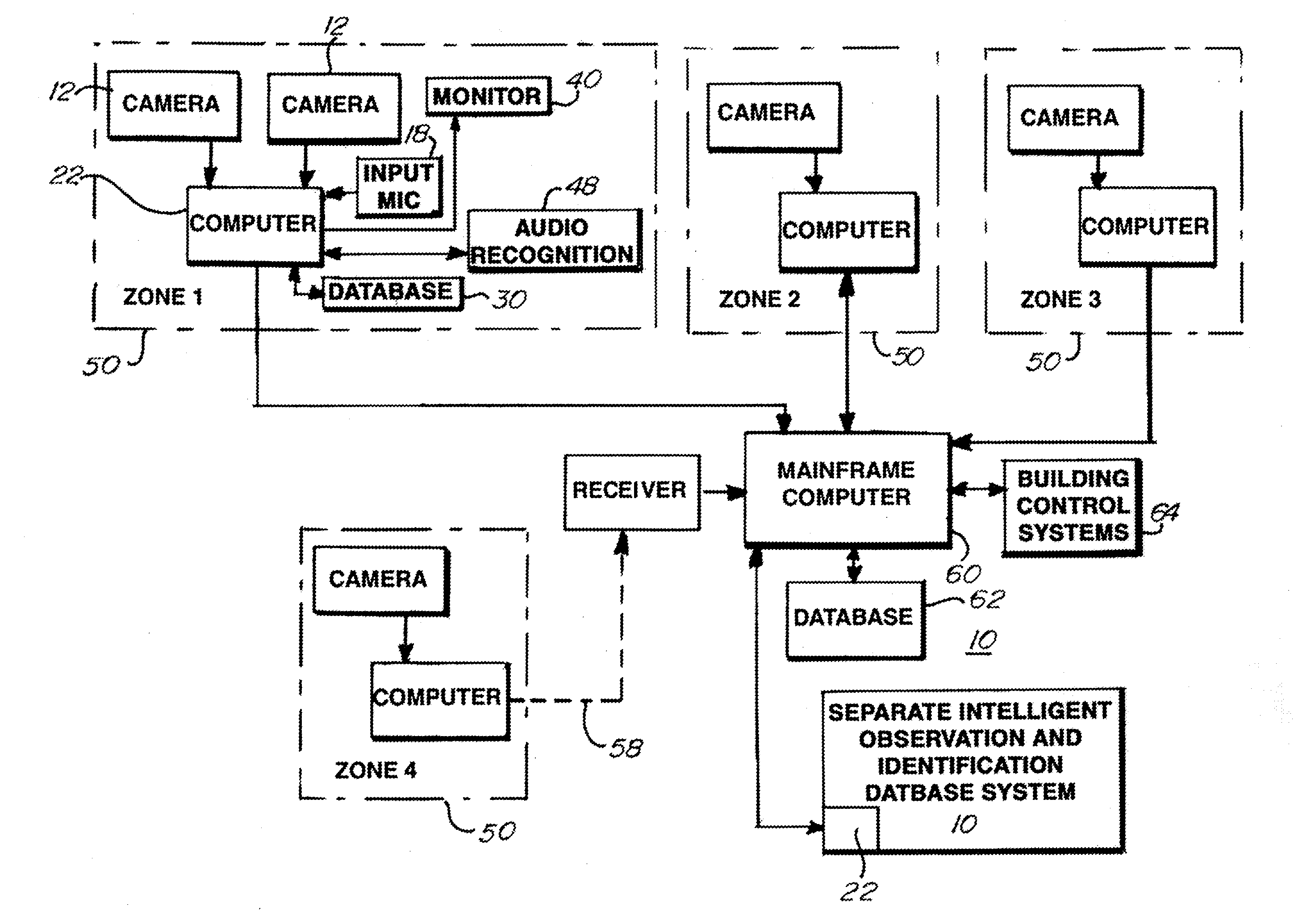
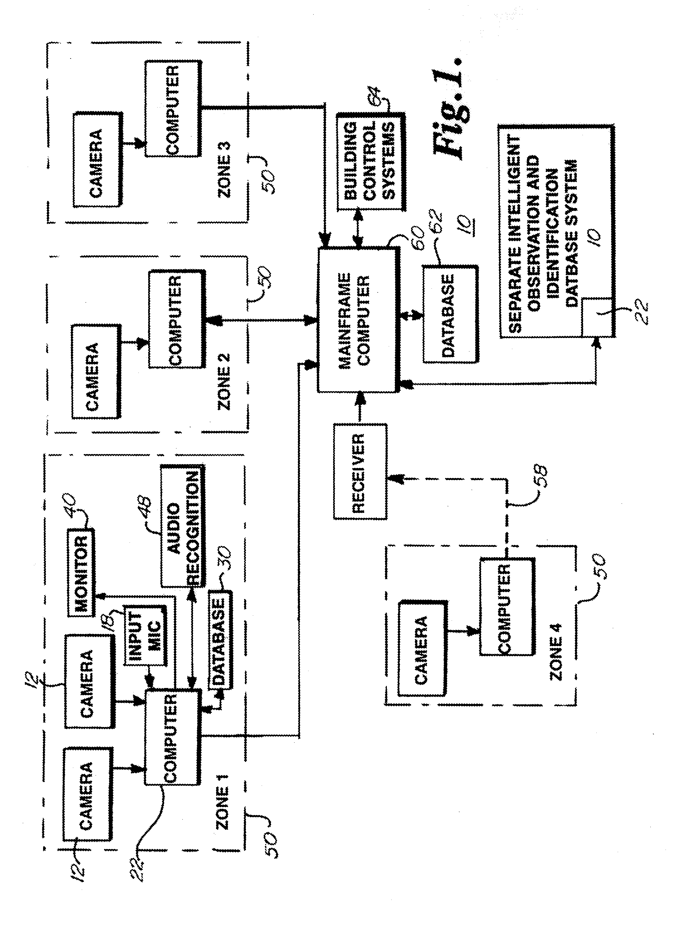
[0023]FIG. 1 shows a schematic view of one embodiment of an intelligent video / audio observation and identification database system according to the present invention.

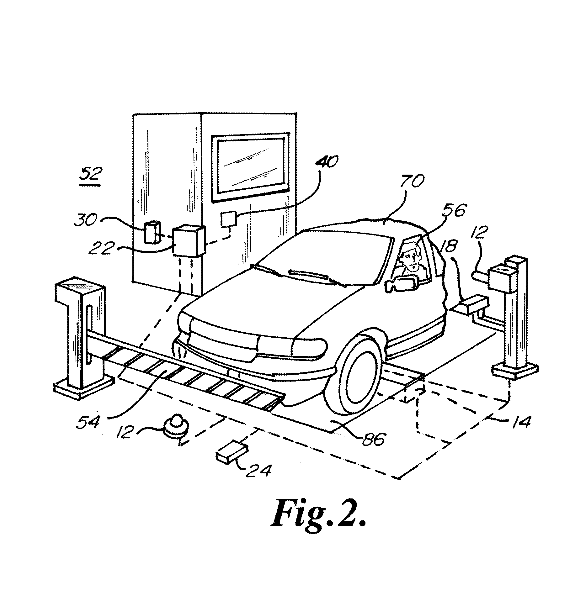
[0024]FIG. 2 depicts one embodiment of an actual installation of an intelligent video / audio observation and identification database system according to the present invention.

[0025]FIG. 2A depicts one embodiment of the intelligent video / audio observation and identification database system according to the present invention.

[0026]FIG. 3 depicts one embodiment of a mobile intelligent observation and identification database system according to the present invention.

[0027]FIG. 4 depicts one embodiment of a comparison of vehicle undercarriage images.

[0028]FIG. 4A depicts one embodiment of a comparison of vehicle undercarriage images.

[0029]FIG. 5 depicts one embodiment of a mobile vehicle undercarriage observation and identification database system.

[0030...


PUM


Abstract

An intelligent video/audio observation and identification database system may define a security zone or group of zones. The system may identify vehicles and individuals entering or exiting the zone through image recognition of the vehicle or individual as compared to prerecorded information stored in a database. The system may alert security personnel as to warrants or other information discovered pertaining to the recognized vehicle or individual resulting from a database search. The system may compare images of a suspect vehicle, such as an undercarriage image, to standard vehicle images stored in the database and alert security personnel as to potential vehicle overloading or foreign objects detected, such as potential bombs. The system may further learn the standard times and locations of vehicles or individuals tracked by the system and alert security personnel upon deviation from standard activity.

Description

CROSS-REFERENCE TO RELATED APPLICATIONS[0001]This application claims the benefit of U.S. Provisional Application 61 / 783,501, filed Mar. 14, 2013 which is a Continuation-In-Part application from U.S. patent application Ser. No. 14 / 033,014 filed Sep. 20, 2013 which is a continuation application from U.S. patent application Ser. No. 13 / 706,824 filed Dec. 6, 2012 now U.S. Pat. No. 8,542,096 which is a Continuation application from U.S. patent application Ser. No. 13 / 479,724 filed May 24, 2012 now issued as U.S. Pat. No. 8,330,599, which is a Continuation application from U.S. patent application Ser. No. 13 / 041,593 filed Mar. 7, 2011 issued as U.S. Pat. No. 8,188,861 on May 29, 2012, which is a Continuation application from U.S. patent application Ser. No. 12 / 254,587, filed Oct. 20, 2008 issued as U.S. Pat. No. 7,902,978; which is a Continuation application from U.S. patent application Ser. No. 10 / 646,853, filed Aug. 22, 2003, issued as U.S. Pat. No. 7,439,847; which claims priority from...

Claims


Application Information

Patent Timeline
Patent Type & Authority Applications(United States)
IPC IPC(8): G06F17/30
CPCG06F17/30247G08B13/19647G08G1/0175G08G1/04G08G1/207G06F16/22G06F16/51G06F16/71G06F16/74G06Q50/265G06V20/52G06V2201/05G06V2201/08
Inventor PEDERSON, JOHN C.
Owner FEDERAL LAW ENFORCEMENT DEV SERVICES
Why Eureka
Try Eureka