Contactless power transfer system for movable object

a technology of movable objects and power transfer systems, which is applied in the direction of electric devices, rail devices, transportation and packaging, etc., can solve the problems of increasing the power transfer loss, posing a risk of ignition or smoke generation, and metal such as steel cans becoming hot in extremely short time periods, etc., and achieves the effect of high degree of accuracy and no delay

Inactive Publication Date: 2014-08-28
TECHNOVA
View PDF7 Cites 56 Cited by
  • Summary
  • Abstract
  • Description
  • Claims
  • Application Information

AI Technical Summary

Benefits of technology

[0054]A contactless power transfer system for a movable object of the present invention is able to detect, with a high degree of accuracy, a metallic foreign object present on a power transmission coil and to remove that metallic foreign object.
[0055]Hence, even if a metallic foreign object is present on the power transmission coil, the foreign object can be removed in an expeditious manner and contactless power transfer to a movable object can be carried on safely and without any delay.

Problems solved by technology

Since a contactless power transfer system transmits energy on the same principle (of electromagnetic induction) as that of an induction heating cooker, a metal such as a steel can becomes hot in an extremely short period of time.
Hence, in case a combustible material is present in the vicinity, then it poses a risk of ignition or smoke generation.
When a metallic foreign object produces heat, it implies an increase in the power transfer loss (=transmitted electrical power-received electrical power) during contactless power transfer.
In that case too, if a metallic foreign object such as a coin or a pin is present in between the power transmission coil and the power reception coil, the metallic foreign object produces heat thereby threatening the safety of the product.
However, if the difference between electrical power values is exceeding the specified value, then the power transmitting side stops the transmission of electrical power.

Method used


Image

  • Contactless power transfer system for movable object
  • Contactless power transfer system for movable object
  • Contactless power transfer system for movable object

Examples


first embodiment

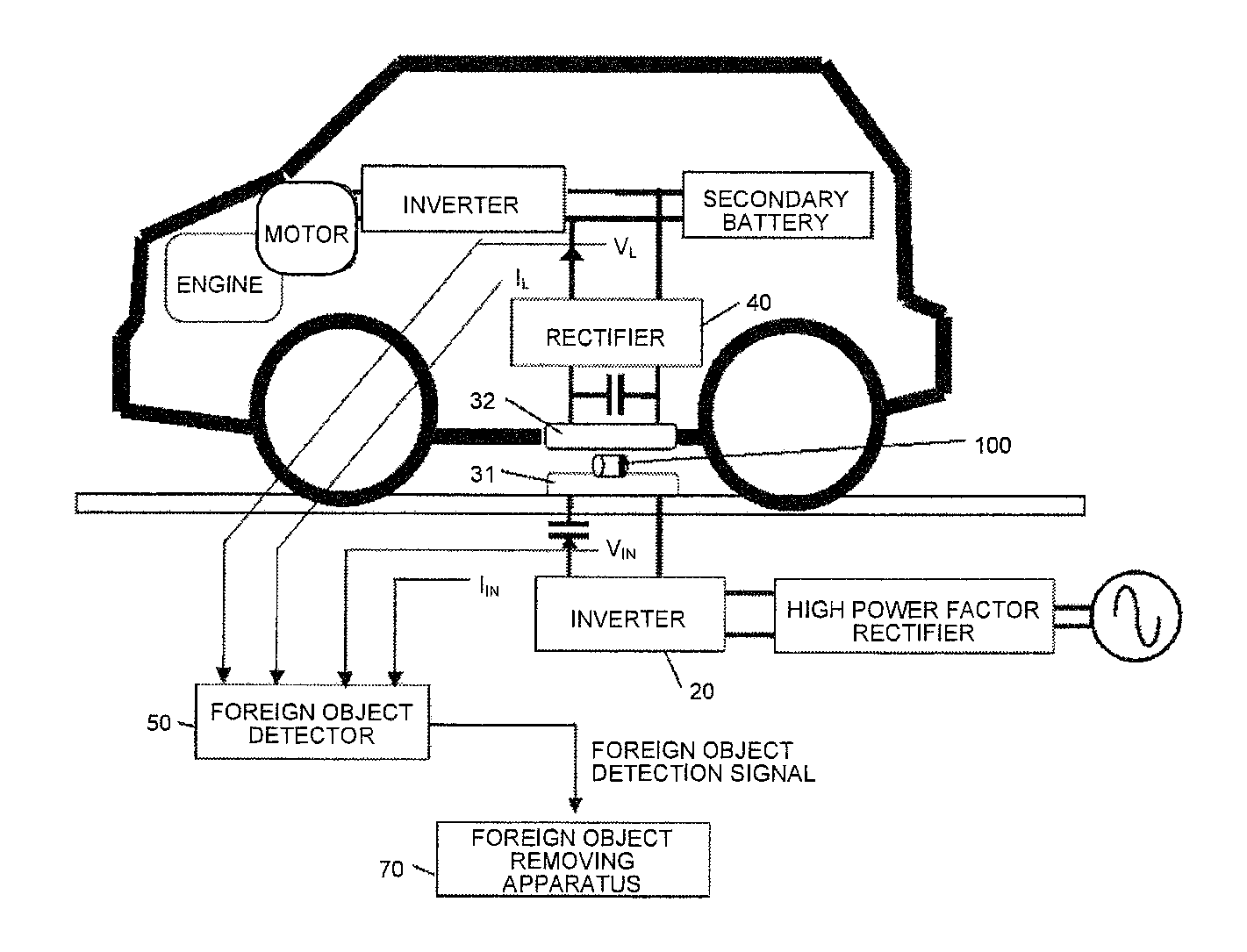
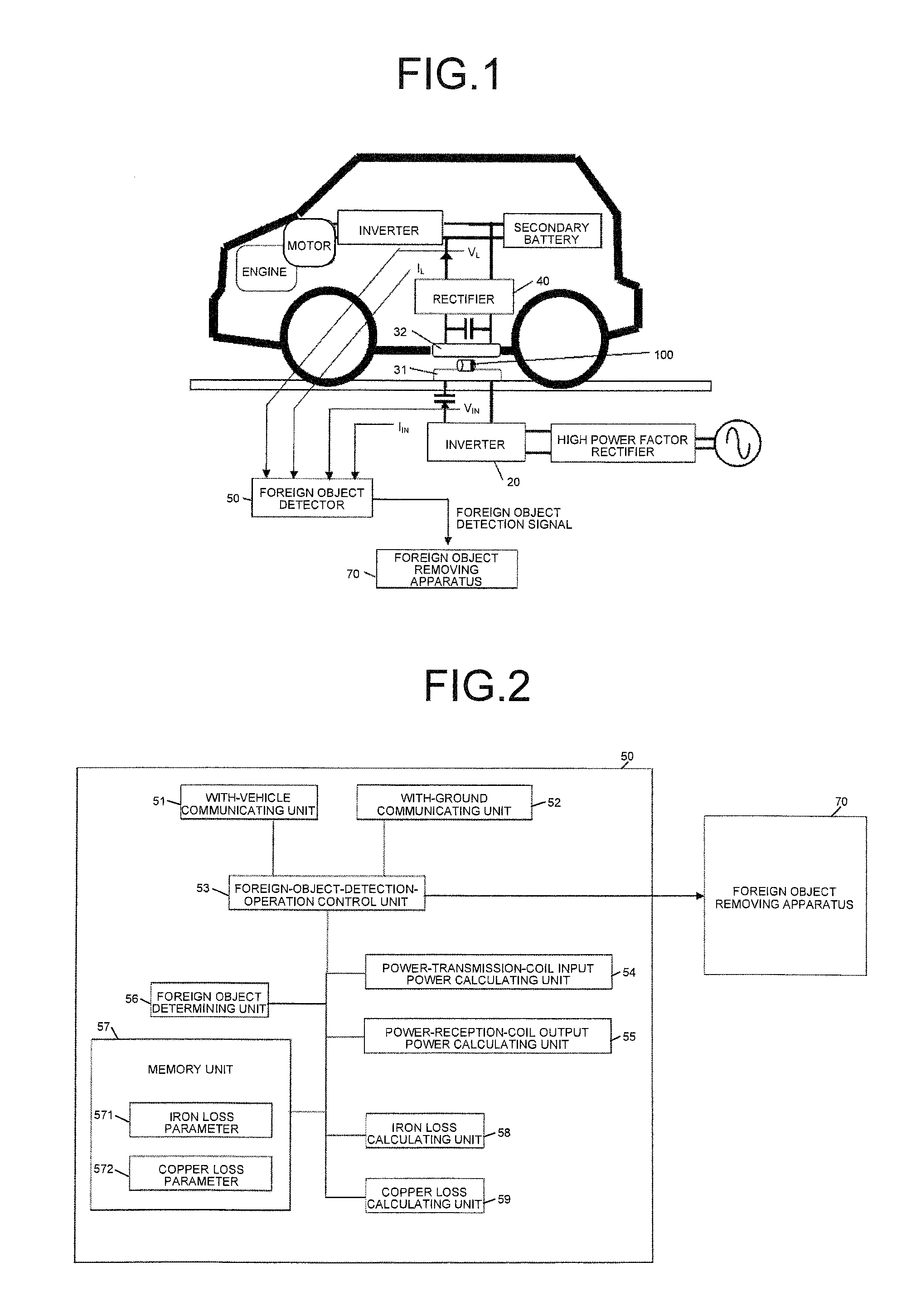
[0071]FIG. 1 schematically illustrates a contactless power transfer system for a movable object according to a first embodiment of the present invention.

[0072]This apparatus includes: a foreign object detector 50 (in the scope of patent claims, a “foreign object detecting unit”) that detects a metallic foreign object 100 present in between the power transmission coil 31 and the power reception coil 32 of a contactless power transfer system; and a foreign object removing apparatus 70 (in the scope of patent claims, a “foreign object removing unit”) that, when a metallic foreign object is detected by the foreign object detector 50, removes the metallic foreign object 100 from the power transmission coil 31.

[0073]With the aim of detecting a metallic foreign object, the foreign object detector 50 obtains, from the ground side, information of an output voltage VIN and an output current IIN of the inverter 20 that are equivalent to the input voltage and the input current of the contactles...

second embodiment

[0102]FIG. 5 schematically illustrates a contactless power transfer system for a movable object according to a second embodiment of the present invention. In this apparatus, before a vehicle is parked over the power transmission coil 31, the metallic foreign object 100 is detected by the foreign object detector 50 and is then removed by the foreign object removing apparatus 70.

[0103]Herein, although the configuration of the foreign object detector 50 is identical to the configuration according to the first embodiment (FIG. 2), the only difference is that the operations of the power-reception-coil output power calculating unit 55 are not carried out.

[0104]FIG. 6 is an operation flowchart of the foreign object detector 50.

[0105]In a state in which no metallic foreign object is present on the power transmission coil 31, the standard value Ps is measured and recorded in advance in the memory unit 57 (Step 21).

[0106]When a target vehicle for contactless power transfer moves closer, the g...

third embodiment

[0117]In a third embodiment of the present invention, the explanation is given about a configuration of the foreign object removing apparatus 70.

[0118]The foreign object removing apparatus illustrated in FIG. 7 includes: a single cover member 81 that covers the upper face of the power transmission coil 31; a pivoting mechanism 82 that pivotally supports the cover member 81 at an edge position of the power transmission coil 31; and a rotary drive apparatus 83 that, when a foreign object detection signal is input from the foreign object detector 50, rotates the pivotally-supported cover member 81 by a predetermined angle.

[0119]The pivoting mechanism 82 pivotally supports the cover member 81 in such a way that the cover member 81 is able to rotate around the axis line parallel to the upper face of the power transmission coil 31.

[0120]The cover member 81 is made of a material such as reinforced resin that is non-magnetic and non-conductive in nature and that has excellent mechanical str...


PUM


Abstract

In an example of a system, power is transferred from a transmission coil to a reception coil by electromagnetic induction. A detecting unit calculates a difference between a standard value and a measured value, detects presence of a metallic foreign object on the transmission coil based on the difference, and outputs a signal when the metallic foreign object is detected. The standard value is obtained by supplying electrical power to the transmission coil when a metallic foreign object is absent on the transmission coil. The measured value is obtained by supplying electrical power to the transmission coil. If PIN0 represents input power of the transmission coil, PL0 represents output power of the reception coil, Pc1 represents copper loss of the transmission coil, and Pc2, represents copper loss of the reception coil, the detecting unit uses a value expressed by (PIN0-PL0-Pc1-Pc2) as the standard value and the measured value.

Description

TECHNICAL FIELD[0001]The present invention relates to a contactless power transfer system for a movable object that performs contactless power transfer from a ground-based power transmission coil to a movable object such as an electrical vehicle including a power reception coil, thereby enables detection as well as removal of metallic foreign objects present on the power transmission coil.BACKGROUND ART[0002]A contactless power transfer system makes use of electromagnetic induction between a power transmission coil (a primary coil) and a power reception coil (a secondary coil) constituting a contactless power transfer transformer to supply electrical power from the power transmission coil to the power reception coil. As illustrated in FIG. 12, a contactless power transfer system for a movable object, which makes use of the contactless power transfer system mentioned above for charging the secondary battery installed in an electrical vehicle or a plug-in hybrid vehicle, includes, on ...

Claims


Application Information

Patent Timeline
Patent Type & Authority Applications(United States)
IPC IPC(8): H02J17/00B60L5/00B60L50/16B60M7/00
CPCH02J17/00B60L3/0069B60L3/04B60L2210/30B60L2210/40B60L2250/10Y02T90/12Y02T90/14B60L2240/36B60L2270/147Y02T10/70Y02T10/7072H02J50/12H02J50/90B60L50/16B60L53/36B60L53/124H02J50/60B60L53/122B60L53/126H02J2310/48Y02T10/72H02J50/80H02M1/0085H02J50/10
Inventor ABE, SHIGERUYASUDA, TOMIOSUZUKI, AKIRAHOSOI, NOBUHIRO
Owner TECHNOVA
Why Eureka
Try Eureka