Cast-in-Place Fiber Technology

a fiber optic and cast-in-place technology, applied in the direction of roads, instruments, traffic signals, etc., can solve the problems of significant costs and difficulty in justifying the cost of laying very small diameter fiber optics

Active Publication Date: 2014-09-18
CENTURYLINK INTPROP +1
View PDF10 Cites 46 Cited by
  • Summary
  • Abstract
  • Description
  • Claims
  • Application Information

AI Technical Summary

Benefits of technology

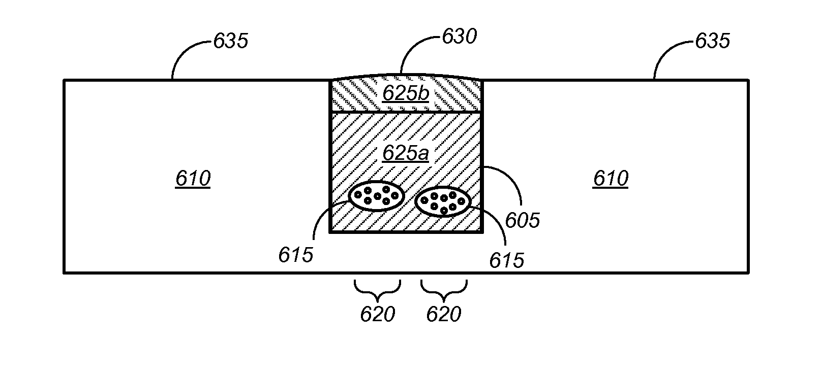
[0012]Merely by way of example, the channel might have a width of between about 0.5 inches and about 12 inches, a width of between about 1 inch and about 6 inches, a width of between about 1.5 inches and about 2.5 inches, or a width of between about 0.5 inches and about 1 inch. In some embodiments, the channel might have a depth of no greater than about 3 inches, a depth of no greater than about 1 inch, or a depth of no greater than about 0.5 inches. In some cases, the one or more lines might comprise at least one optical fiber. In some instances, the one or more lines might comprise at least one power line.
[0013]Merely by way of example, in some embodiments, the capping material might comprise two or more sealant materials. The two or more sealant materials might, in some cases, comprise a bottom sealant material filling a bottom portion of the channel and a top sealant material filling a top portion of the channel above the bottom sealant material. The bottom sealant material might comprise polyurea and the top sealant material might comprise a material selecte...

Problems solved by technology

While trenchless methods greatly reduce the surface disturbance, they are associated with significant costs.
While these costs can be justified for the placement of natural gas lines or water mains, where the vendor has exclusivity and is a...

Method used


Image

  • Cast-in-Place Fiber Technology
  • Cast-in-Place Fiber Technology
  • Cast-in-Place Fiber Technology

Examples


Embodiment Construction

[0021]While various aspects and features of certain embodiments have been summarized above, the following detailed description illustrates a few exemplary embodiments in further detail to enable one of skill in the art to practice such embodiments. The described examples are provided for illustrative purposes and are not intended to limit the scope of the invention.

[0022]In the following description, for the purposes of explanation, numerous specific details are set forth in order to provide a thorough understanding of the described embodiments. It will be apparent to one skilled in the art, however, that other embodiments of the present invention may be practiced without some of these specific details. In other instances, certain structures and devices are shown in block diagram form. Several embodiments are described herein, and while various features are ascribed to different embodiments, it should be appreciated that the features described with respect to one embodiment may be i...


PUM


Abstract

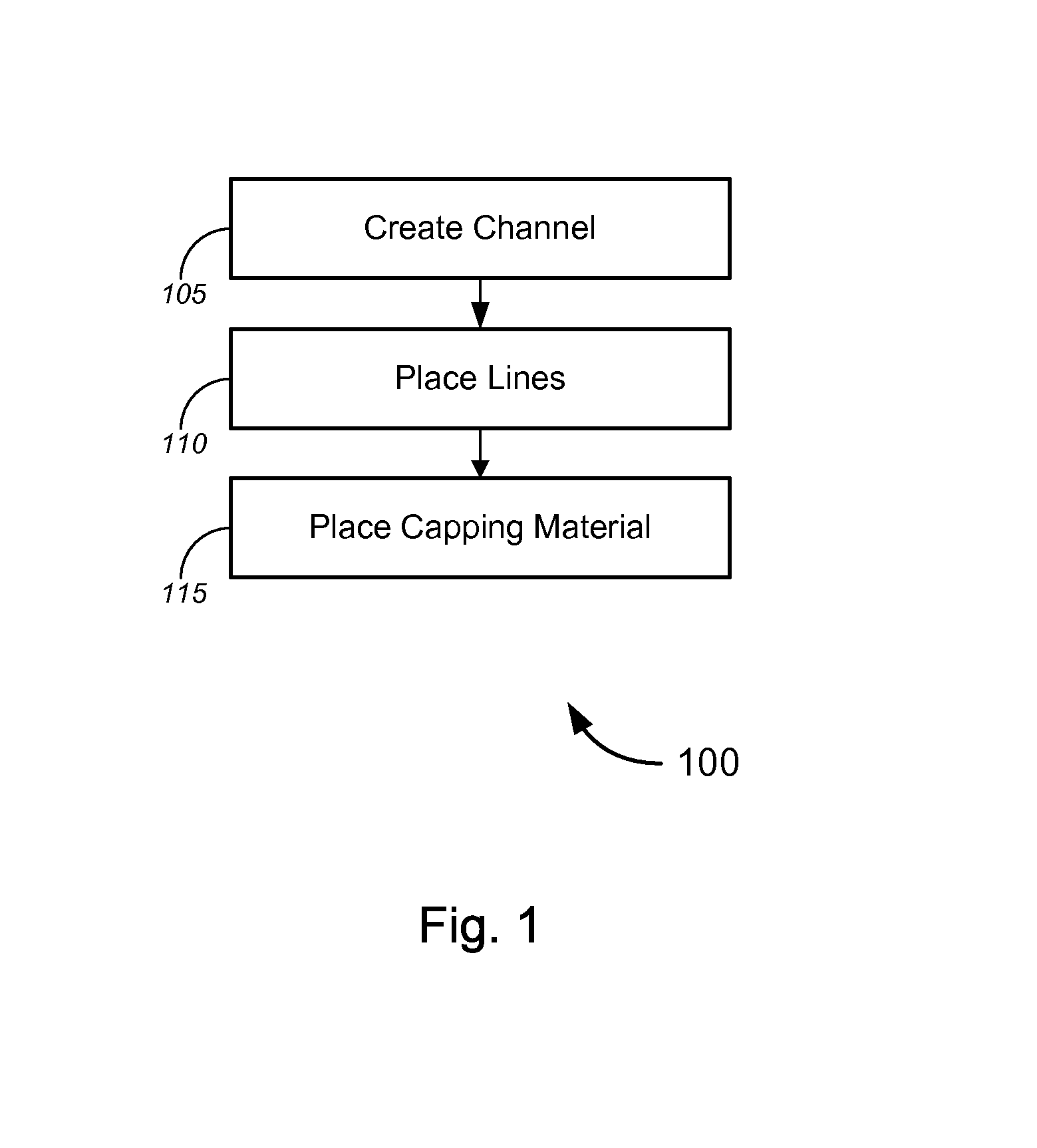
Novel tools and techniques for installing lines or cables, including, without limitation, power lines, low voltage lines, telecommunications lines or cables (e.g., telephone cables, network cables, television cables, etc.), and/or the like, and, in particular, installing optical fiber and/or other lines, slightly below ground level in a roadway or other ground surface. In some cases, a method might include creating a channel in the ground surface, placing one or more lines (e.g., power lines, low voltage lines, telecommunications lines, and/or the like) in the channel, and placing a capping material in the channel, thereby encapsulating the lines. In some cases, placing the one or more lines in the channel might include placing a conduit (containing the one or more lines) in the channel, and encapsulating the one or more lines might include encapsulating the conduit. The capping material might include polyurea, thermosetting material, and/or any other suitable material.

Description

CROSS-REFERENCES TO RELATED APPLICATIONS[0001]This application claims priority to U.S. Patent Application Ser. No. 61 / 793,514 (the “'514 application”), filed Mar. 15, 2013 by Erez R. Allouche et al. (attorney docket no. 020370-009801US), entitled, “Cast-in-Place Fiber Technology,” the entire disclosure of which is incorporated herein by reference in its entirety for all purposes.COPYRIGHT STATEMENT[0002]A portion of the disclosure of this patent document contains material that is subject to copyright protection. The copyright owner has no objection to the facsimile reproduction by anyone of the patent document or the patent disclosure as it appears in the Patent and Trademark Office patent file or records, but otherwise reserves all copyright rights whatsoever.FIELD[0003]The present disclosure relates, in general, to a method and apparatus pertaining to installation of optical fiber, and, more particularly, to a method of installing optical fiber in a ground surface (including witho...

Claims


Application Information

Patent Timeline
IPC IPC(8): F16L1/028E01F9/04F16L1/06
CPCF16L1/028F16L1/06E01F9/042E01F11/00E02F5/10G02B6/504E01C23/09H02G9/00
Inventor ALLOUCHE, EREZ N.CADY, BRYANELFORD, MICHAEL L.
Owner CENTURYLINK INTPROP
Why Eureka
Try Eureka