Dynamic residue clearing control with in-situ profile control (ISPC)

a technology of in-situ profile control and residue clearing, which is applied in the direction of superfinishing machines, manufacturing tools, lapping machines, etc., can solve the problems that existing optical monitoring techniques may not meet the increasing demands of semiconductor device manufacturers, and it is not possible to determine the polishing endpoint merely

Active Publication Date: 2014-09-18
APPLIED MATERIALS INC
View PDF5 Cites 12 Cited by
  • Summary
  • Abstract
  • Description
  • Claims
  • Application Information

AI Technical Summary

Benefits of technology

[0009]Implementations of the present invention generally relate to the monitoring and control of a chemical mechanical polishing process. In one implementation, a method for polishing a substrate is provided. The method comprises polishing a substrate having a plurality of zones to remove a bulk material layer in a polishing apparatus having a rotatable platen, wherein a polishing rate of each zone of the plurality of zones is independently controllable by an independently variable polishing parameter, storing a bulk target index value, measuring a first sequence of values from each zone of the plurality of zones during polishing with an in-situ monitoring system, for each zone of the plurality of zones, fitting a first linear function to the first sequence of values, for a reference zone from the plurality of zones, determining a projected bulk endpoint time at which the reference zone will reach the bulk target index value based on the first linear function of the reference zone, for at least one adjustable zone of the plurality of zones, calculating a first adjustment for the polishing parameter for the adjustable zone to adjust the polishing rate of the adjustable zone such that the adjustable zone is closer to the bulk target index value at the projected bulk endpoint time than without such adjustment, the calculation including calculating the adjustment based on an error value calculated for a previous substrate, after adjustment of the polishing parameter, for each zone, during polishing measuring a second sequence of values obtained after the first adjustment of the polishing parameter, for the at least one adjustable zone of each substrate, fitting a second linear function to the second sequence of values, calculating the error values for a subsequent substrate for the at least one adjustable zone based on the second linear function and a desired slope, determining a projected clearing endpoint time for removal of a residual material that either the first or second linear function of the reference zone will reach a clearing target index value, for at least one adjustable zone, calculating a second adjustment for the polishing parameter for the adjustable zone to adjust the polishing rate of the adjustable zone such that the adjustable zone is closer to the clearing target index value at the projected clearing endpoint time than without such adjustment, the calculation including calculating the adjustment based on an error value calculated for a previous substrate, continue polishing the plurality of zones to remove the bulk material layer until the bulk endpoint time passes and polishing the plurality of zones to remove the residual material layer using the second adjusted polishing parameter such that the adjustable zone is closer to the clearing target index value at the projected clearing endpoint.

Problems solved by technology

One problem in CMP is using an appropriate polishing rate to achieve a desirable profile, e.g., a substrate layer that has been planarized to a desired flatness or thickness, or a desired amount of material has been removed.
Therefore, it may not be possible to determine the polishing endpoint merely as a function of the polishing time, or to achieve a desired profile merely by applying a constant pressure.
However, existing optical monitoring techniques may not satisfy increasing demands of semiconductor device manufacturers.

Method used


Image

  • Dynamic residue clearing control with in-situ profile control (ISPC)
  • Dynamic residue clearing control with in-situ profile control (ISPC)
  • Dynamic residue clearing control with in-situ profile control (ISPC)

Examples


Embodiment Construction

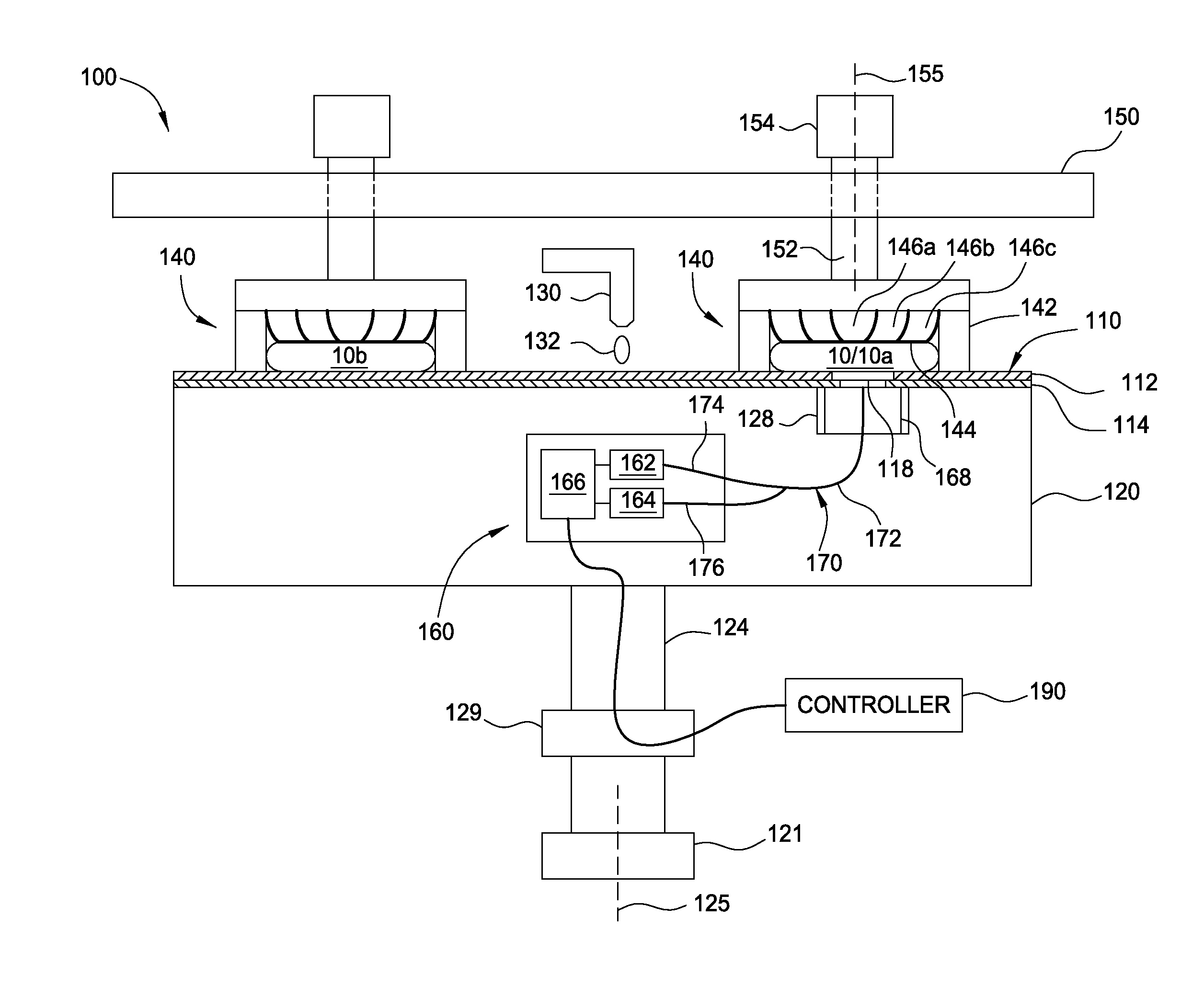
[0032]Implementations described herein generally relate to the monitoring and control of a chemical mechanical polishing process. The implementations described herein address the dynamic control of the residue clearing step of CMP processes such as shallow trench isolation (“STI”) and replacement metal gate (“RMG”) interlayer dielectric (“ILD”). Motor torque endpoint (“MT EP”) and dynamic in-situ profile control (“ISPC”) are currently used to control the bulk CMP polishing recipe prior to the residue clearing process. During the residue clearing process, the same bulk CMP polishing recipe is used to control the clearing process. Since ISPC typically targets a flat post profile before the clearing process begins, the ISPC pressures used during the bulk CMP polishing process tend to cause over-correction during the clearing process.

[0033]The implementations described herein provide several approaches for controlling the residue clearing process of the CMP polish. Dynamic ISPC is used ...


PUM


Abstract

A method for controlling the residue clearing process of a chemical mechanical polishing (“CMP”) process is provided. Dynamic in-situ profile control (“ISPC”) is used to control polishing before residue clearing starts, and then a new polishing recipe is dynamically calculated for the clearing process. Several different methods are disclosed for calculating the clearing recipe. First, in certain implementations when feedback at T0 or T1 methods are used, a post polishing profile and feedback offsets are generated in ISPC software. Based on the polishing profile and feedback generated from ISPC before the start of the clearing process, a flat post profile after clearing is targeted. The estimated time for the clearing step may be based on the previously processed wafers (for example, a moving average of the previous endpoint times). The calculated pressures may be scaled to a lower (or higher) baseline pressure for a more uniform clearing.

Description

CROSS-REFERENCE TO RELATED APPLICATIONS[0001]This application claims benefit of U.S. Provisional Patent Application Ser. No. 61 / 787,221, filed Mar. 15, 2013, which is herein incorporated by reference in its entirety.BACKGROUND[0002]1. Field[0003]Embodiments of the present invention generally relate to the monitoring and control of a chemical mechanical polishing process.[0004]2. Description of the Related Art[0005]An integrated circuit is typically formed on a substrate by the sequential deposition of conductive, semiconductive, or insulative layers on a silicon wafer. One fabrication step involves depositing a filler layer over a non-planar surface and planarizing the filler layer. For certain applications, the filler layer is planarized until the top surface of a patterned layer is exposed. A conductive filler layer, for example, can be deposited on a patterned insulative layer to fill the trenches or holes in the insulative layer. After planarization, the portions of the conducti...

Claims


Application Information

Patent Timeline
Patent Type & Authority Applications(United States)
IPC IPC(8): B24B37/005
CPCB24B37/005B24B35/005
Inventor QIAN, JUNDHANDAPANI, SIVAKUMARCHERIAN, BENJAMINOSTERHELD, THOMAS H.GARRETSON, CHARLES C.
Owner APPLIED MATERIALS INC
Why Eureka
Try Eureka