Communication system, communication apparatus, and communication method

Active Publication Date: 2014-09-18
NEC CORP
View PDF2 Cites 2 Cited by
  • Summary
  • Abstract
  • Description
  • Claims
  • Application Information

AI Technical Summary

Benefits of technology

[0009]The power consumption of the master apparatus can be reduced by intermittently performing the operation of waiting for receipt of the connection request. However, the timing of making the connection request usually varies depending on the apparatus that makes the connection request. Therefore, there is a problem in which the power is not efficiently consumed accor

Problems solved by technology

However, even if the technique disclosed in Patent Literature 1 is used, the power saving of the master apparatus cannot be realized when the master apparatus waits for a connection request.
Therefore, there is a p

Method used


Image

  • Communication system, communication apparatus, and communication method
  • Communication system, communication apparatus, and communication method
  • Communication system, communication apparatus, and communication method

Examples


first exemplary embodiment

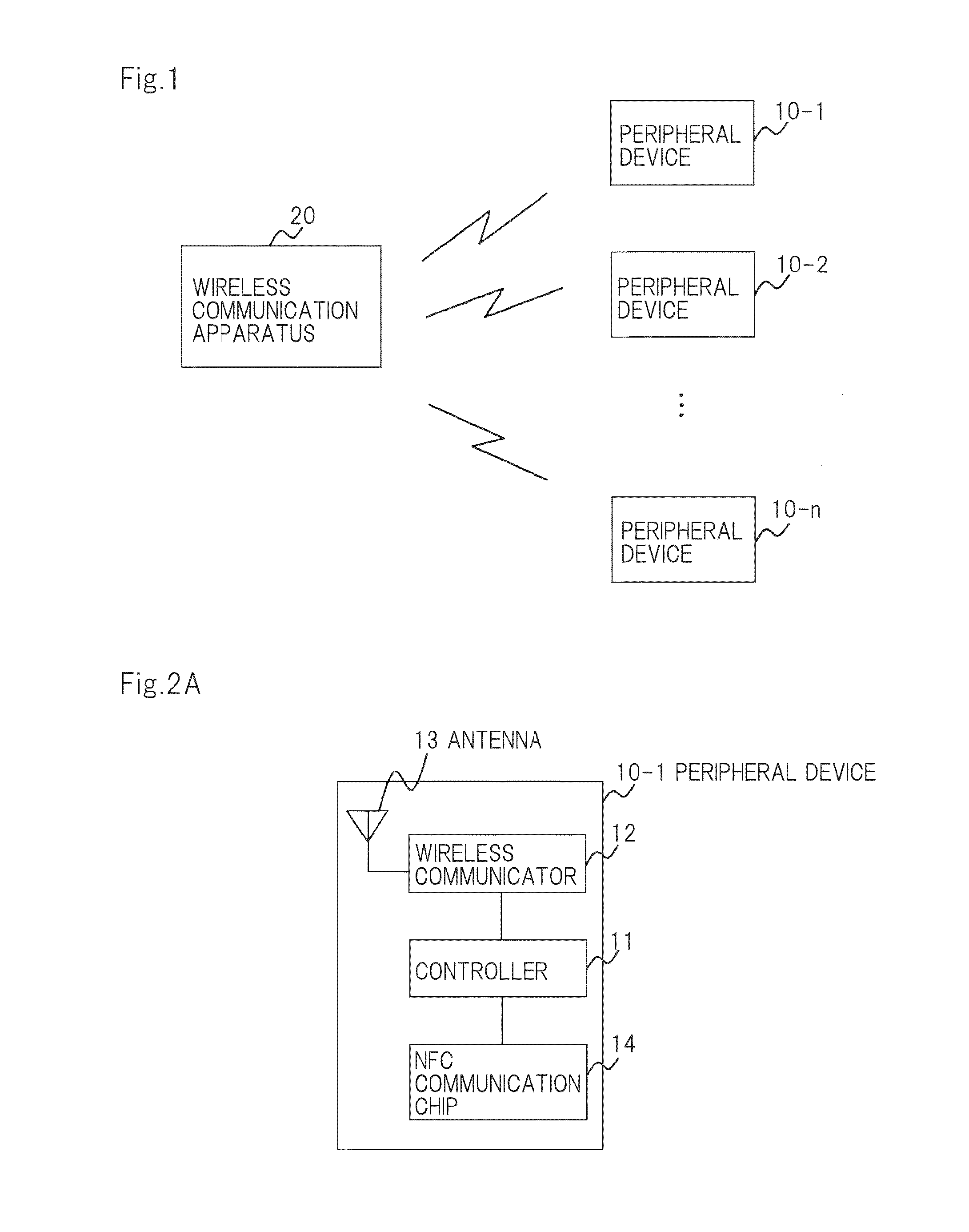
[0050]FIG. 1 is a block diagram showing a configuration of a first exemplary embodiment of a wireless communication system of the present invention.

[0051]As shown in FIG. 1, the wireless communication system of the exemplary embodiment includes peripheral devices 10-1 to 10-n that are transmission source communication apparatuses and wireless communication apparatus 20 that is a transmission destination communication apparatus.

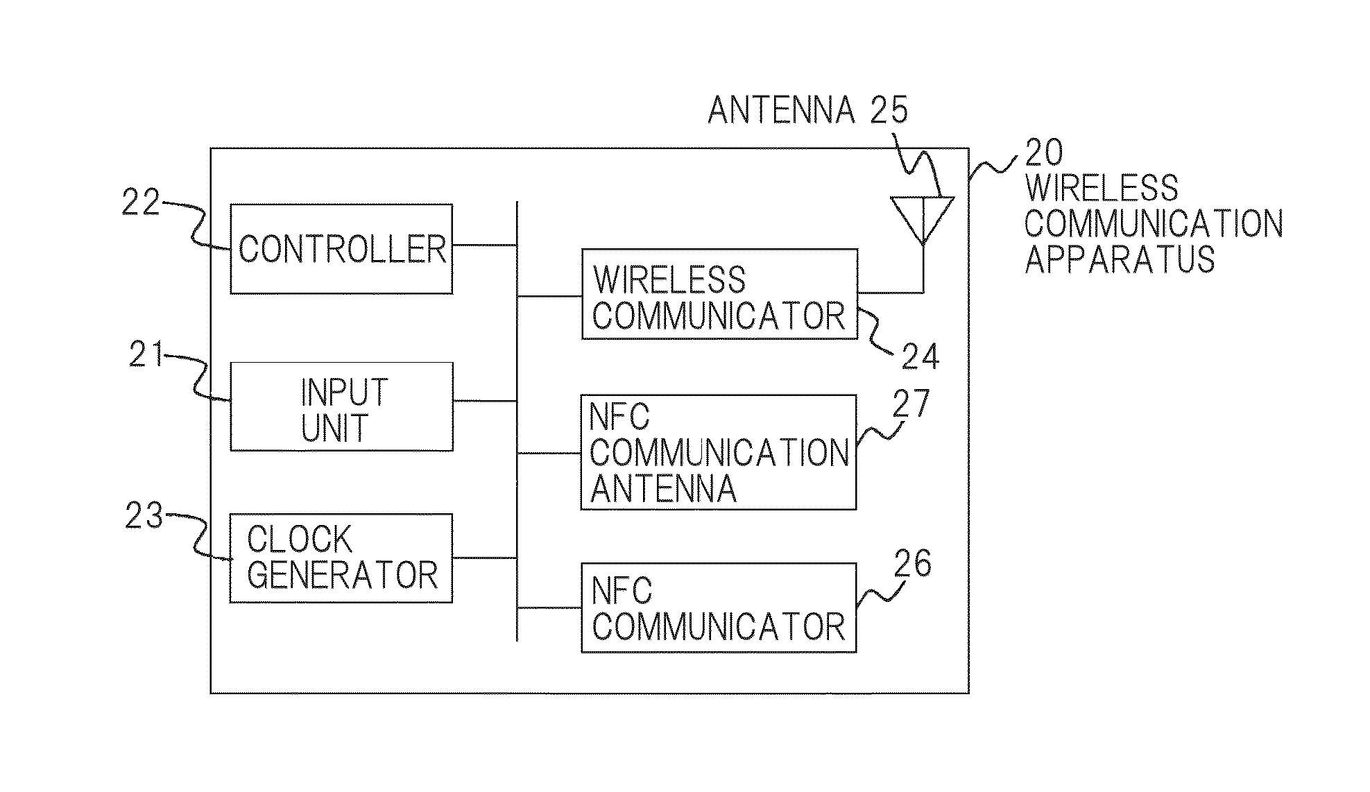
[0052]Wireless communication apparatus 20 performs an operation of waiting for receipt of a connection request frame including a connection request command transmitted from each of peripheral devices 10-1 to 10-n to establish connection with peripheral devices 10-1 to 10-n. Specifically, the operation of waiting for receipt of the connection request frame is a scan operation of monitoring the connection request frame. When connection with peripheral devices 10-1 to 10-n is established, wireless communication apparatus 20 transmits predetermined information to ...

second exemplary embodiment

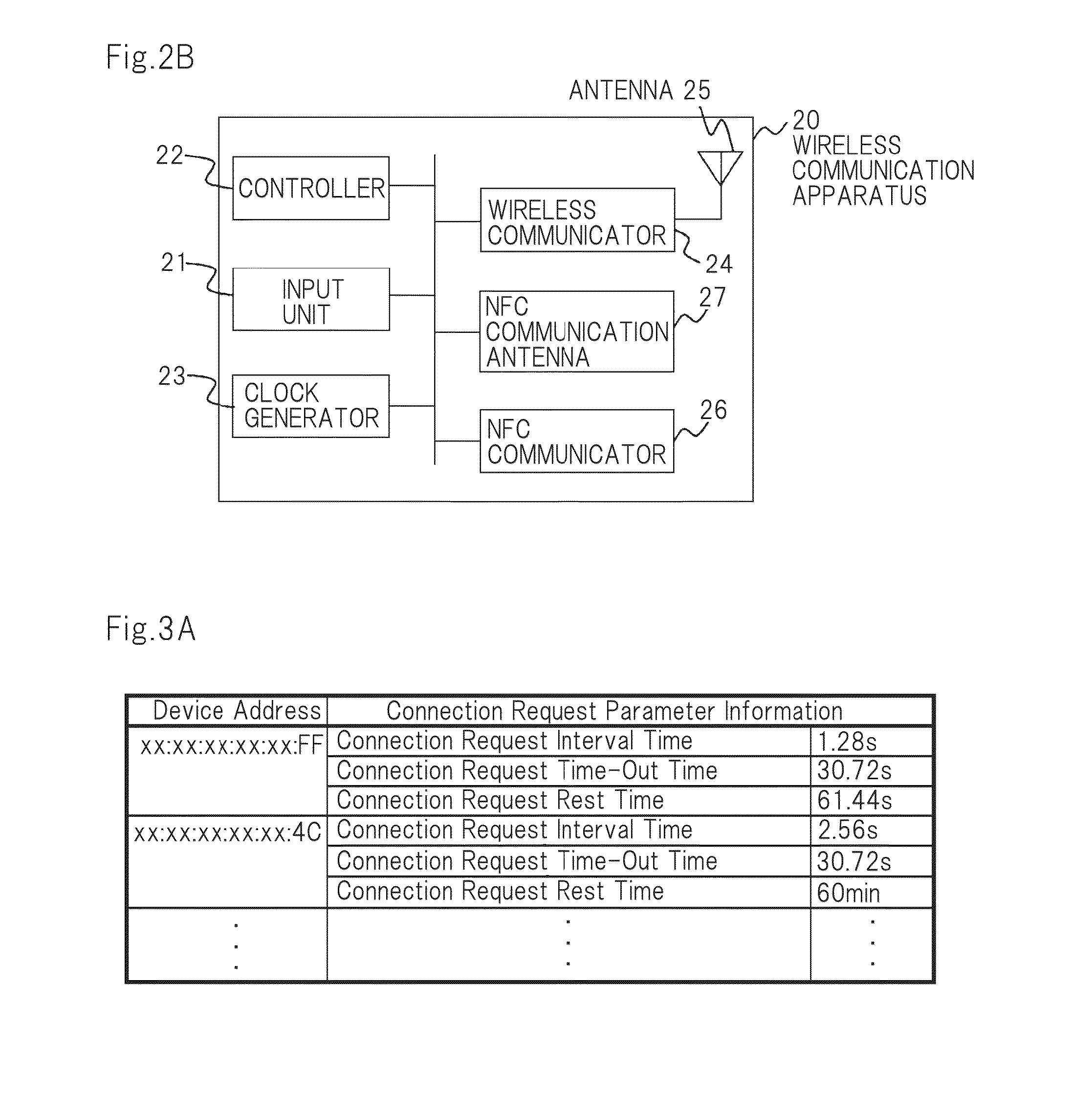
[0124]In the first exemplary embodiment, the case in which wireless communication apparatus 20 acquires the connection request parameter information by using NFC communication has been described.

[0125]In the present exemplary embodiment, a case in which wireless communication apparatus 20 acquires the connection request parameter information by receiving the connection request frame will be described.

[0126]FIG. 6 is a block diagram showing a configuration of a secondary exemplary embodiment of the wireless communication system of the present invention.

[0127]As shown in FIG. 6, the wireless communication system according to the exemplary embodiment includes wireless terminals 50-1 to 50-n that are transmission source communication apparatuses and wireless communication apparatus 60 that is a transmission destination communication apparatus.

[0128]Wireless terminals 50-1 to 50-n and wireless communication apparatus 60 shown in FIG. 6 are different from peripheral devices 10-1 to 10-n a...


PUM


Abstract

Provided is a communication system that includes a plurality of communication apparatuses and that transmits and receives a connection request command between the plurality of communication apparatuses to establish a connection between the plurality of communication apparatuses, wherein a transmission source communication apparatus as a transmission source of the connection request command from among the plurality of communication apparatuses transmits transmission timing information that indicates timing at which the connection request command is transmitted, and a transmission destination communication apparatus as a transmission destination of the connection request command from among the plurality of communication apparatuses receives the transmission timing information transmitted from the transmission source communication apparatus and determines timing at which an operation of waiting for receipt of the connection request command transmitted from the transmission source communication apparatus is performed based on the timing indicated by the received transmission timing information.

Description

TECHNICAL FIELD[0001]The present invention relates to a communication system including a communication apparatus that makes a connection request for establishing a connection and including a communication apparatus that performs an operation of waiting for receipt of a connection request.BACKGROUND ART[0002]There are low-power-consumption wireless communication techniques, such as Zig Bee and Bluetooth Low Energy, used to exchange low-capacity information every certain time. “Zig Bee” and “Bluetooth” are both registered trademarks.[0003]In such a wireless communication technique, when a master apparatus and a slave apparatus establish a connection for communication, the slave apparatus just needs to make a request for connection to the master apparatus only when communication is required. Therefore, power saving can be realized in the slave apparatus.[0004]On the other hand, the master apparatus does not know when the slave apparatus will make the connection request, and the master ...

Claims


Application Information

Patent Timeline
IPC IPC(8): H04W76/02H04M1/72412
CPCH04W76/02H04W52/0209H04W52/0229H04W52/0251H04M2250/02H04M2250/04H04W52/0216H04W76/10Y02D30/70H04M1/72412
Inventor TAKAYANAGI, ASAKO
Owner NEC CORP
Why Eureka
Try Eureka