Electrode with charge-operated indicator

Inactive Publication Date: 2014-09-18
WELCH ALLYN INC
View PDF11 Cites 38 Cited by
  • Summary
  • Abstract
  • Description
  • Claims
  • Application Information

AI Technical Summary

Benefits of technology

[0014]According to another aspect of the present invention, there is provided a method of making a patient-contact device for a medical sensing system, the method including arranging first and second electrical contacts over a support; electrically connecting a charge-holding structure between the first and second electrical contacts; arranging an indicator over the support, the indicator coupled to the charge-holding structure so that the indicator changes state in response to a change in the charge stored in the charge-holding structure; and charging the charge-holding structure so that the indicator has a first visual appearance.
[0015]An advantage that

Problems solved by technology

As a result, wires can readily be attached to the wrong electrodes.
Electrode adhesives can have a limited shelf life, after which they will no longer adequately adhere to the subject.
An issue is that loose electrodes are not readily identified by the caregiver, creating significant delays and errors in the examination process, whether in the course of a scheduled medical examination in a medical facility or in situations in which an apparatus such as a Holter assembly is worn for longer periods of time.
However, this scheme does not permit determining the quality of the connection between the electrode and the patient's skin.
Even if the gel is in operable condition, it can still fail to make effective electrical contact with the patient due to hair, sweat, skin oil, skin flakes, dirt, or other contaminants on the skin, misapplication of the electrode,

Method used


Image

  • Electrode with charge-operated indicator
  • Electrode with charge-operated indicator
  • Electrode with charge-operated indicator

Examples


Embodiment Construction

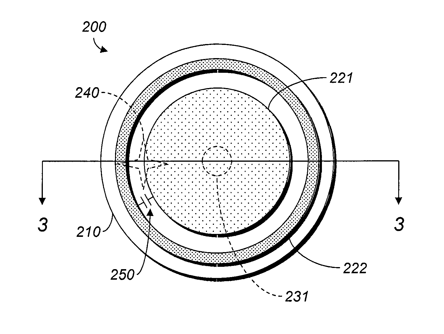
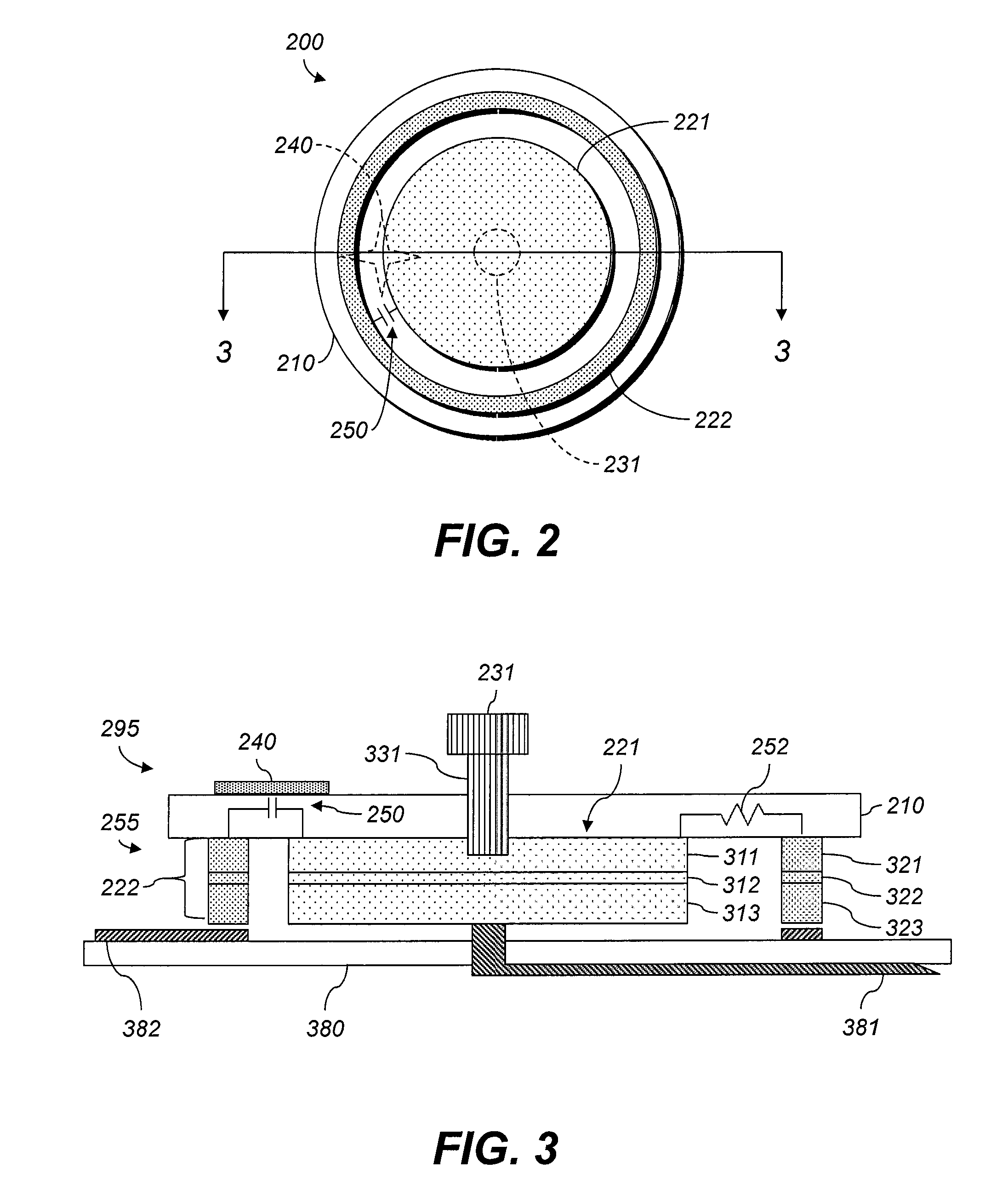
[0030]Throughout this disclosure, the terms “top” and “bottom” are exemplary and not limiting. Generally speaking, the term “bottom” will refer to the side of an electrode facing the subject when the electrode is in use.

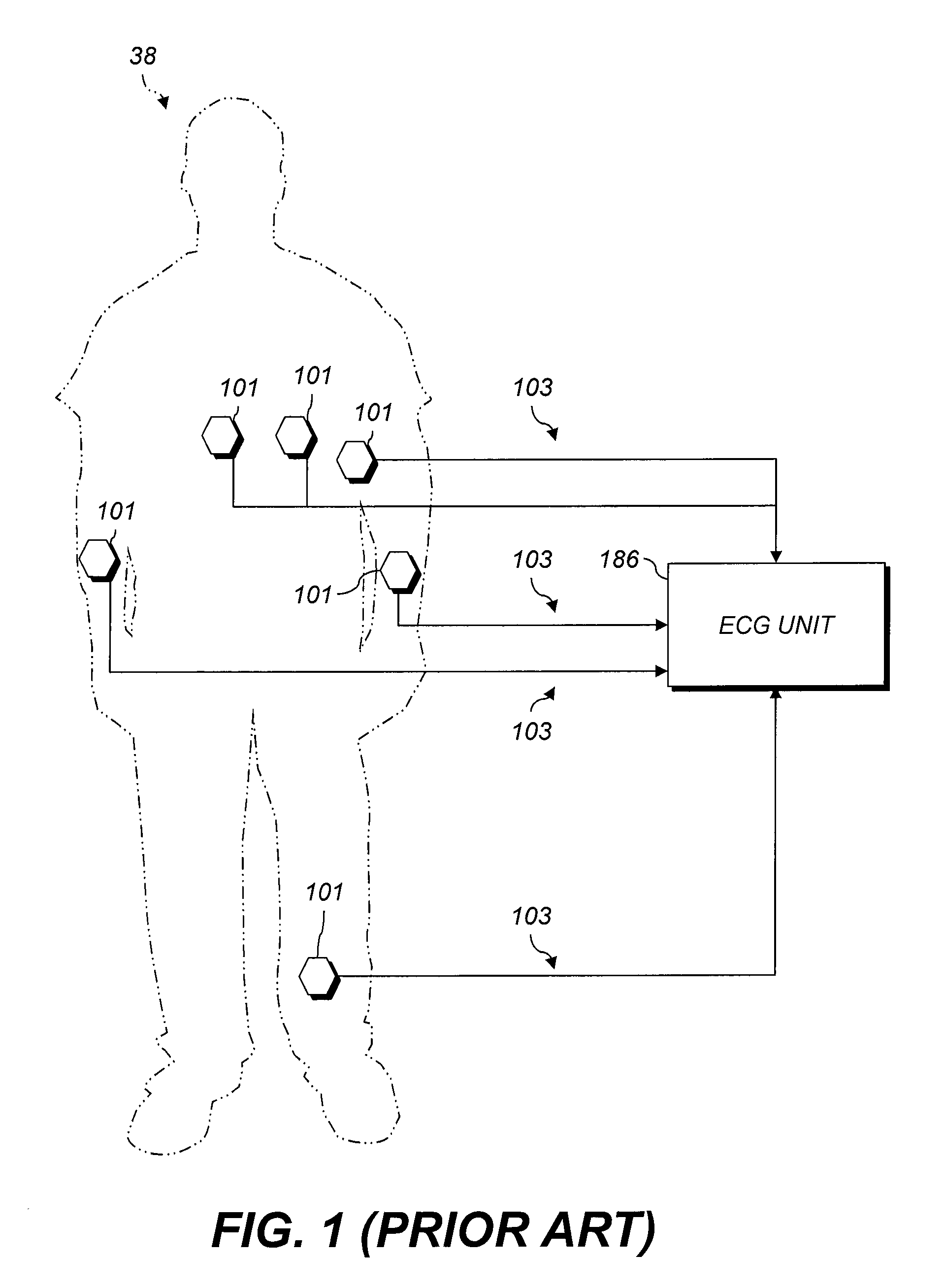
[0031]The following description relates to exemplary embodiments of patient-contact electrodes as well as use thereof in monitoring patient condition using a specific medical sensing apparatus, e.g., by taking electrocardiograms (ECGs). However, it will be readily apparent that the herein described concepts can be used with other apparatus that includes electrodes that are adhered to a patient, such as body temperature patches. Still further and in order to provide a suitable frame of reference with regard to the accompanying drawings, certain terms are used throughout. These terms are not intended to narrow the scope of the concepts detailed herein, including those embodied in the claims unless specifically indicated. In addition and in the following description, so...


PUM


Abstract

An electrode includes separate first and second electrical contacts to contact the skin of a subject. A charge-holding structure is electrically connected between the first and second contacts. An indicator is operatively coupled to the charge-holding structure so that the indicator changes visibly in response to a change in the charge stored in the charge-holding structure. The electrode can include a rectifier across the contacts. A container for electrodes includes an electrical supply and a plurality of receptacles for electrodes so that a voltage difference is maintained across conductors of each receptacle (and contacts of an electrode therein) for at least one week. A method of making electrodes includes arranging the contacts over a support, connecting the charge-holding structure between them, arranging the indicator over the support, and charging the charge-holding structure so that the indicator has a first visual appearance.

Description

TECHNICAL FIELD[0001]The present application generally relates to the field of diagnostic patient examination and more specifically relates to skin-contacting electrodes used in medical examination devices to measure properties of subjects or their environments, e.g., electrical activity.BACKGROUND[0002]An electrocardiogram (ECG) monitoring apparatus is a medical device that receives and processes ECG signals generated by a circulatory system of a person, e.g., the electrical impulses that trigger various phases of a heartbeat. The apparatus typically includes a plurality of patient-contact electrodes (“electrodes,”“skin-contact biopotential electrodes,” or “SCBEs”), each electrically connected via a wire to a voltage detector. The patient-contact electrodes make physical contact with the person being monitored, e.g., on the person's skin. The ECG electrodes and wires receive and relay ECG signals generated by the person to components of the ECG monitoring apparatus that process the...

Claims


Application Information

Patent Timeline
IPC IPC(8): A61B5/0408A61B5/0205A61B5/01A61B5/044
CPCA61B5/04087A61B5/01A61B2562/0257A61B5/74A61B2560/0462A61B5/7221A61B5/259A61B5/28
Inventor LANE, JOHN A.FREER, BENJAMINQUINN, DAVID E.KROON, FREDERIK W.
Owner WELCH ALLYN INC
Why Eureka
Try Eureka