Systems and methods for providing alignment in total knee arthroplasty

a technology of total knee arthroplasty and system and method, applied in the field of surgical procedures, can solve problems such as accuracy limitations, mechanical devices, and bone drill guides

Active Publication Date: 2014-09-18
ARTHROMEDA
View PDF5 Cites 33 Cited by
  • Summary
  • Abstract
  • Description
  • Claims
  • Application Information

AI Technical Summary

Benefits of technology

[0023]The systems and methods described herein address the problems discussed above by providing more accurate and more precise alignment of anatomical structures, prostheses, and surgical tools during total knee arthroplasty (TKA) operations. In general, the systems and methods described herein employ a plurality of sensor units capable of detecting their position and orientation in space and communicating that information to a digital data processor. By attaching the sensors to any of a patient's bone, a calibration instrument, a cutting guide, or other surgical tools, software executing on the digital data processor can determine the three-dimensional position of, for example, the patient's bones (e.g., the femur and tibia), the cutting guides, or other tools / instruments. The positions of one or more of these components can be updated continuously throughout the operation, and can aid surgeons in more efficiently and more accurately completing a TKA procedure. The systems and methods described herein have a number of advantages over the prior art, including increased accuracy and precision, as well as reduced cost due to simple configuration and the use of readily-available components. In addition, the systems and methods described herein can be easily reused with multiple patients without requiring the fabrication of custom components.
[0032]In such embodiments, the first bone can be a tibia and the second bone can be a femur. Accordingly, the method can provide a surgeon with valuable feedback regarding the orientations of each bone.
[0036]In such embodiments, the first bone can be a tibia and the second bone can be a femur. Accordingly, the method can provide a surgeon with valuable feedback regarding the orientations of each bone. In addition, any of the various features or embodiments described above can be combined in any of a variety of manners, even if not stated explicitly here.

Problems solved by technology

Mechanical devices, on the other hand, can have accuracy limitations that result from being positioned visually and without a precise calibration.

Method used


Image

  • Systems and methods for providing alignment in total knee arthroplasty
  • Systems and methods for providing alignment in total knee arthroplasty
  • Systems and methods for providing alignment in total knee arthroplasty

Examples


Embodiment Construction

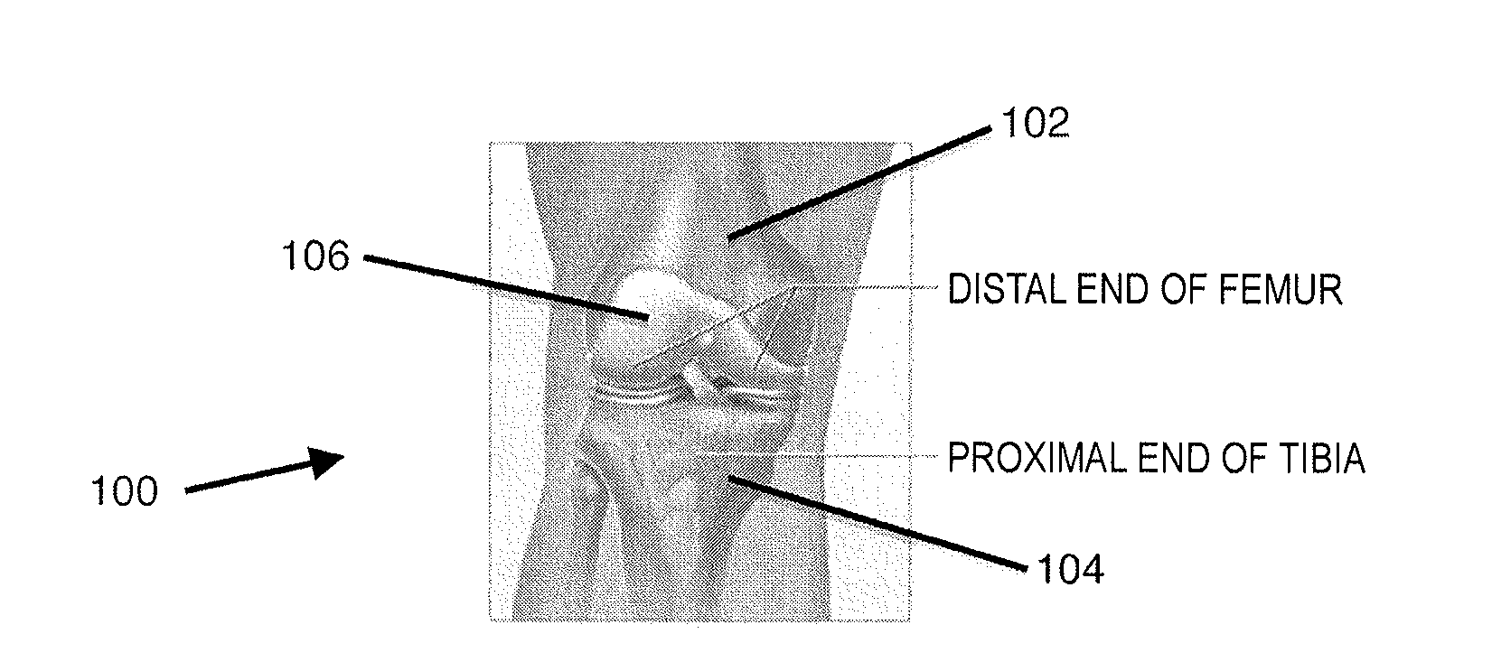
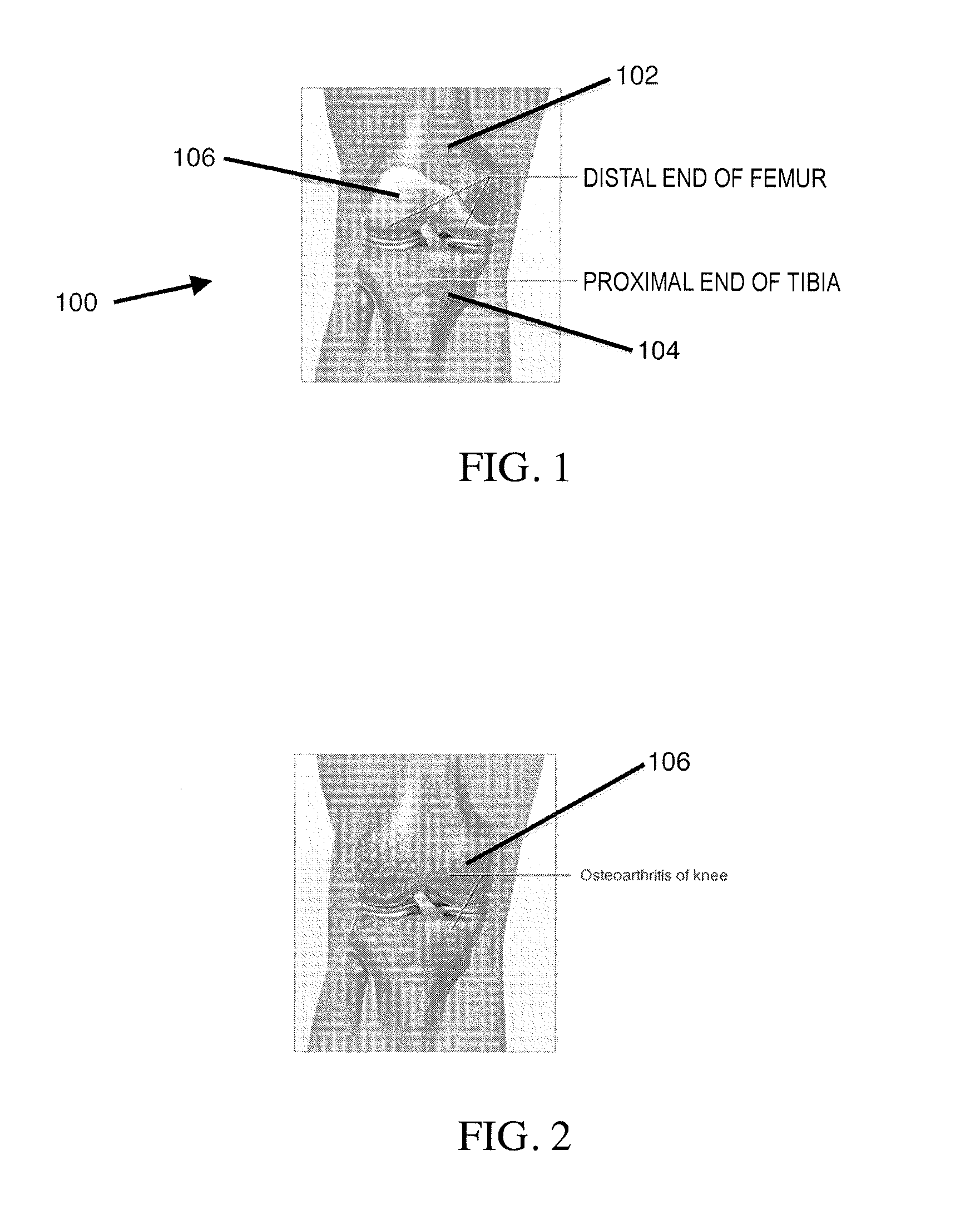
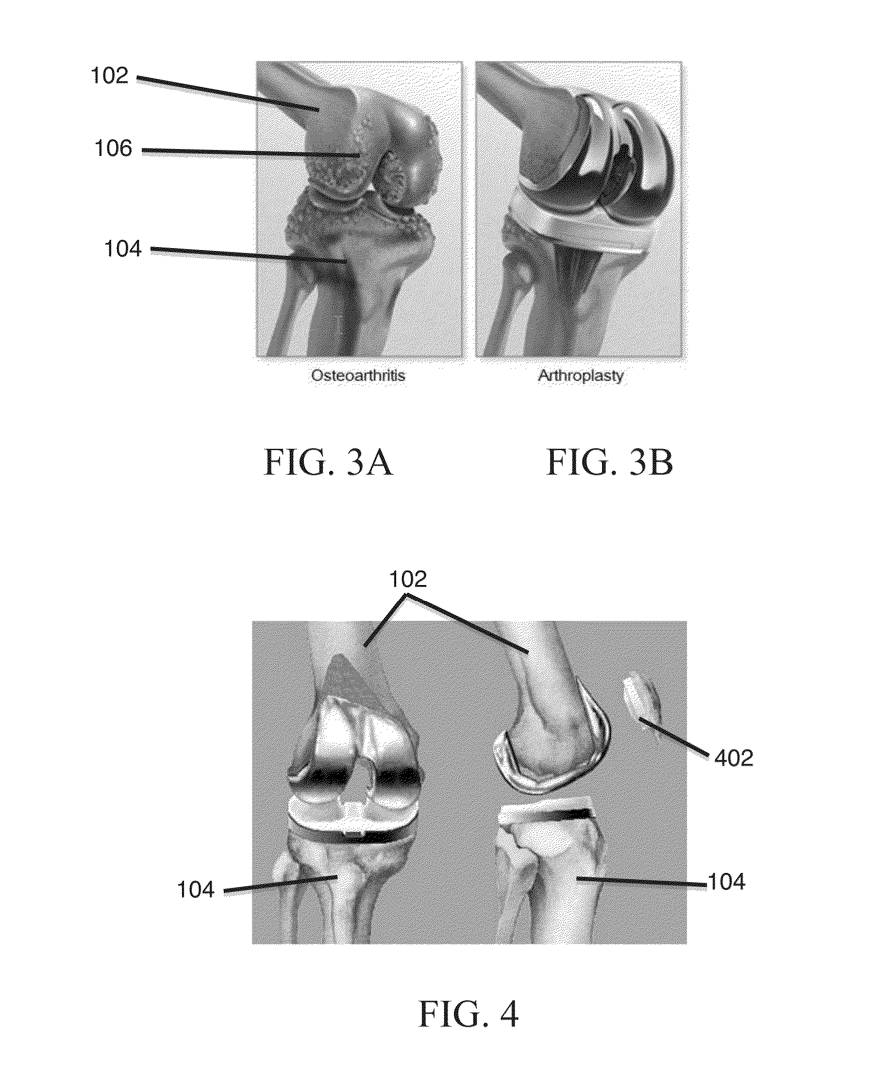
[0063]The instant invention includes a novel apparatus, as well as a unique methodology and system, to measure, calculate, and monitor alignment of the long bones of the human lower limb for precise intra-operative bone preparation and positioning of prostheses, particularly with respect to avoiding misalignment of the reconstructed knee joint.

[0064]The systems described herein generally include a plurality of measuring sensor units that can detect their position and orientation in three-dimensional space and communicate this information to a digital data processor, e.g., via a wireless communication protocol. The measuring sensor units described herein can utilize inexpensive, highly accurate, digital components that are able to communicate with software running on a computer processor, personal computer (PC), or hand-held electronic device (e.g., a smartphone or electronic tablet), to accurately determine three-dimensional positioning of the femur and the tibia, as well as the ang...


PUM


Abstract

Systems and methods for providing alignment in total knee arthroplasty operations are provided herein. The systems and methods generally include a plurality of sensors coupled to a patient's bones or other surgical tools, the sensors detect their position and orientation in space and communicate this information to a processor. The processor can utilize the information to display data to a surgeon or other user regarding the position, angle, and alignment of a patient's bones, surgical tools, and the reconstructed knee joint.

Description

FIELD OF THE INVENTION[0001]The present invention relates to surgical procedures and, in particular, to systems and methods for aligning anatomical structures and surgical components during total knee arthroplasty operations.BACKGROUND[0002]Total Knee Arthroplasty[0003]The knee is the largest joint in the human body. As shown in FIGS. 1 and 7A, the knee 100 includes the lower end of the femur 102 (thigh bone), the upper end of the tibia 104 (shin bone), and the inner surface of the patella 106 (knee cap, see FIG. 7A). The femur rotates over the tibia and the patella glides in a groove on the end of the femur in front (i.e., anterior). The inner surface of these bony components is covered by cartilage 106 that, along with joint fluid, provides smooth motion of the joint and shock absorption. Various ligaments and muscles help in keeping the knee strong and stable.[0004]Arthritis is a condition where the cartilage 106 starts wearing away and the knee becomes stiff and painful. FIGS. 2...

Claims


Application Information

Patent Timeline
Patent Type & Authority Applications(United States)
IPC IPC(8): A61F2/46A61B17/17
CPCA61F2/461A61F2002/4632A61B17/1764A61F2/4657A61F2002/4633A61F2002/4668A61B17/155A61B17/157
Inventor AGHAZADEH, MEHRAN S.
Owner ARTHROMEDA
Why Eureka
Try Eureka