Venturi Valve with Hard Stop

a technology of hard stop and venturi valve, which is applied in the direction of valve details, valve housings, pipe elements, etc., can solve the problems of affecting the accuracy of the venturi valve, the deterioration of the multi-rate venturi spring, and the affecting of the pitch, so as to limit the travel of the plunger and maintain accurate control of the air flow.

Inactive Publication Date: 2014-09-25
E H PRICE
View PDF21 Cites 5 Cited by
  • Summary
  • Abstract
  • Description
  • Claims
  • Application Information

AI Technical Summary

Benefits of technology

[0009]In order to solve the problem associated with the deterioration of multi-rate Venturi springs from over compression, a hard stop is positioned on the control shaft to engage the end cap of the plunger and thereby limit the extent of the travel of the plunger. Limiting the travel of the plunger keeps the Venturi spring from becoming over-compressed during extreme conditions (pressure surges outside of normal operating range), thereby assuring that the Venturi spring will maintain its designed force curve and thereby maintaining accurate control of the air flow through the Venturi valve.

Problems solved by technology

Engineered, multi-rate Venturi springs 34 are more susceptible to deterioration and loss of accuracy resulting from over compression because the multi-rate Venturi springs 34 use only a portion of the force curve.
During over-compression, the pitch becomes altered, and Venturi spring's force curve deteriorates rapidly.

Method used


Image

  • Venturi Valve with Hard Stop
  • Venturi Valve with Hard Stop
  • Venturi Valve with Hard Stop

Examples


Embodiment Construction

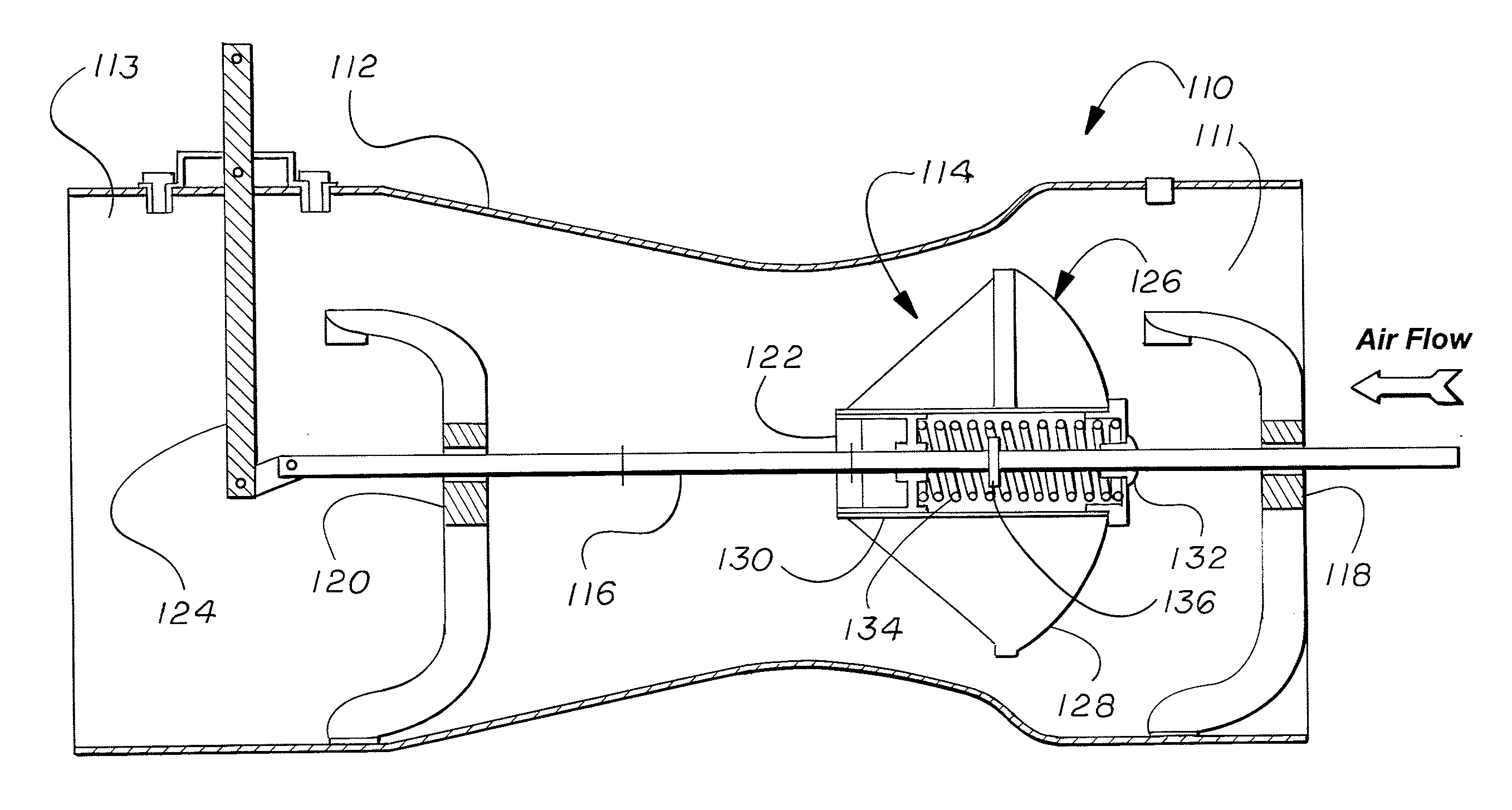
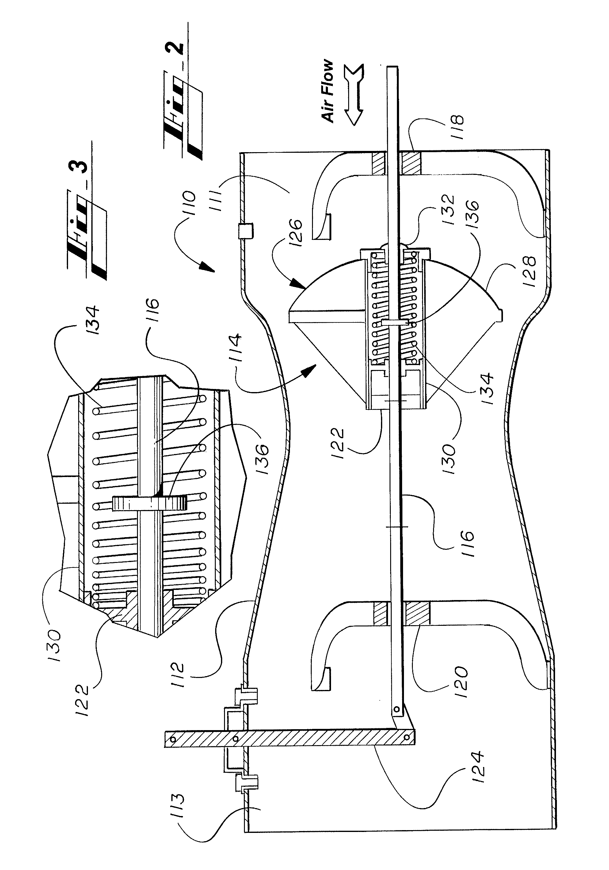
[0014]A Venturi valve 110 in accordance with the present invention is shown in FIGS. 2 and 3. The Venturi valve 110 comprises a Venturi shaped outer housing 112 with an inlet 11, an outlet 13, and an internal plunger assembly 114. The plunger assembly 114 comprises a sliding control shaft mounted on slide bearings 118 and 120. A control arm 124 controls the sliding movement and position of the control shaft 116. A piston 122 is fixed to the control shaft 116 for movement with the control shaft 116. A plunger 126 is slidably mounted on the control shaft. The plunger 126 comprises a plunger body 128 attached to a plunger cylinder 130 having an end cap 132. The plunger cylinder 130 is free to slide over the fixed piston 122, and the end cap 132 is free to slide along the control shaft 116. An engineered, multi-rate compression spring 134 is positioned between the fixed piston 122 and the end cap 132 to control the sliding movement of the plunger 126 along the control shaft 116. A hard ...


PUM


Abstract

A Venturi valve has a Venturi housing with a plunger slidably mounted on a control shaft within the Venturi housing. Sliding movement of the plunger along the control shaft is controlled by a compression spring. A hard stop is fixed to the control shaft to limit the movement of the plunger along the control shaft in order to keep the compression spring from over compression and from a resulting loss of accuracy.

Description

CROSS REFERENCE TO RELATED PATENT APPLICATIONS[0001]This patent application claims priority from U.S. Provisional Patent Application No. 61 / 804,906, filed Mar. 25, 2013, which is hereby incorporated by reference.FIELD OF THE INVENTION[0002]This invention relates to a Venturi valve, and more particularly relates to a spring-loaded plunger for the Venturi valve that controls the flow of air through the Venturi valve.BACKGROUND OF THE INVENTION[0003]Venturi valves are pressure independent flow control valves, suitable for health care and laboratory spaces that require accurate room pressurization and proper directional air flow. The valve assembly consists of a Venturi shaped outer housing and an internal plunger assembly. The plunger assembly maintains constant air flow through the valve at a given set-point or actuator position regardless of changes in static duct pressure.[0004]A conventional Venturi valve 10 is shown in FIG. 1. The conventional Venturi valve 10 comprises a Venturi ...

Claims


Application Information

Patent Timeline
Patent Type & Authority Applications(United States)
IPC IPC(8): F16K27/06
CPCF16K27/062F24F11/75
Inventor NESBITT, MATTHEW JAMES ROYPENNER, JARVIS MATTHEW
Owner E H PRICE
Why Eureka
Try Eureka