Light-emitting diode package and method for manufacturing same

Active Publication Date: 2014-09-25
SEOUL VIOSYS CO LTD
View PDF1 Cites 7 Cited by
  • Summary
  • Abstract
  • Description
  • Claims
  • Application Information

AI Technical Summary

Benefits of technology

The present invention is about a light emitting diode package that can prevent the failure of the lens during bonding. It achieves this by using a bonding agent to seal the cavity and prevent air pressure from separating the transparent member from the package body. The invention also includes an air discharge channel to release air pressure. Overall, this improves the reliability and quality of the light emitting diode package.

Problems solved by technology

Since UV light emitted from such a DUV LED can be easily absorbed by a typical sealing resin such as silicone or epoxy resins, it is difficult to seal the DUV LED using the sealing resin unlike a blue LED.
However, since such a stem package is expensive due to high material and manufacturing costs, attempts have been made to use low cost packages such as ceramic packages or general plastic packages as UV LED packages.
However, during attachment of the lens, the lens can be separated from the package body by compressed air within the cavity, thereby causing bonding failure.
Moreover, upon curing of the bonding agent, air pressure within the cavity can be increased due to expansion of air within the cavity, thereby causing separation of the lens from the package body.

Method used


Image

  • Light-emitting diode package and method for manufacturing same
  • Light-emitting diode package and method for manufacturing same
  • Light-emitting diode package and method for manufacturing same

Examples


Embodiment Construction

[0022]Hereinafter, exemplary embodiments of the present invention will be described in detail with reference to the accompanying drawings. The following embodiments are given by way of illustration to provide a thorough understanding of the present invention to those skilled in the art. Thus, the present invention is not limited to the following embodiments and may be embodied in different ways. It should be understood that the drawings are not to precise scale and some of the dimensions, such as width, length, thickness, and the like, are exaggerated for clarity of description in the drawings. Like elements are denoted by like reference numerals throughout the specification and drawings.

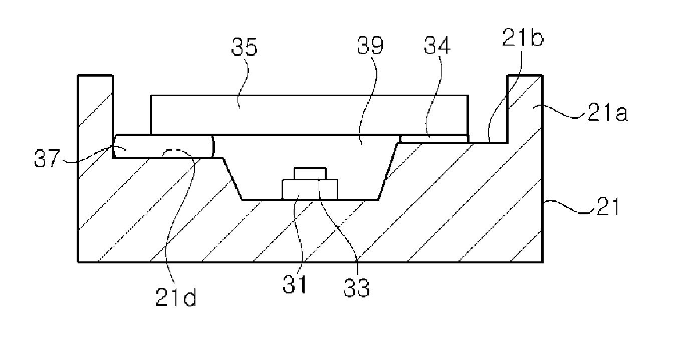
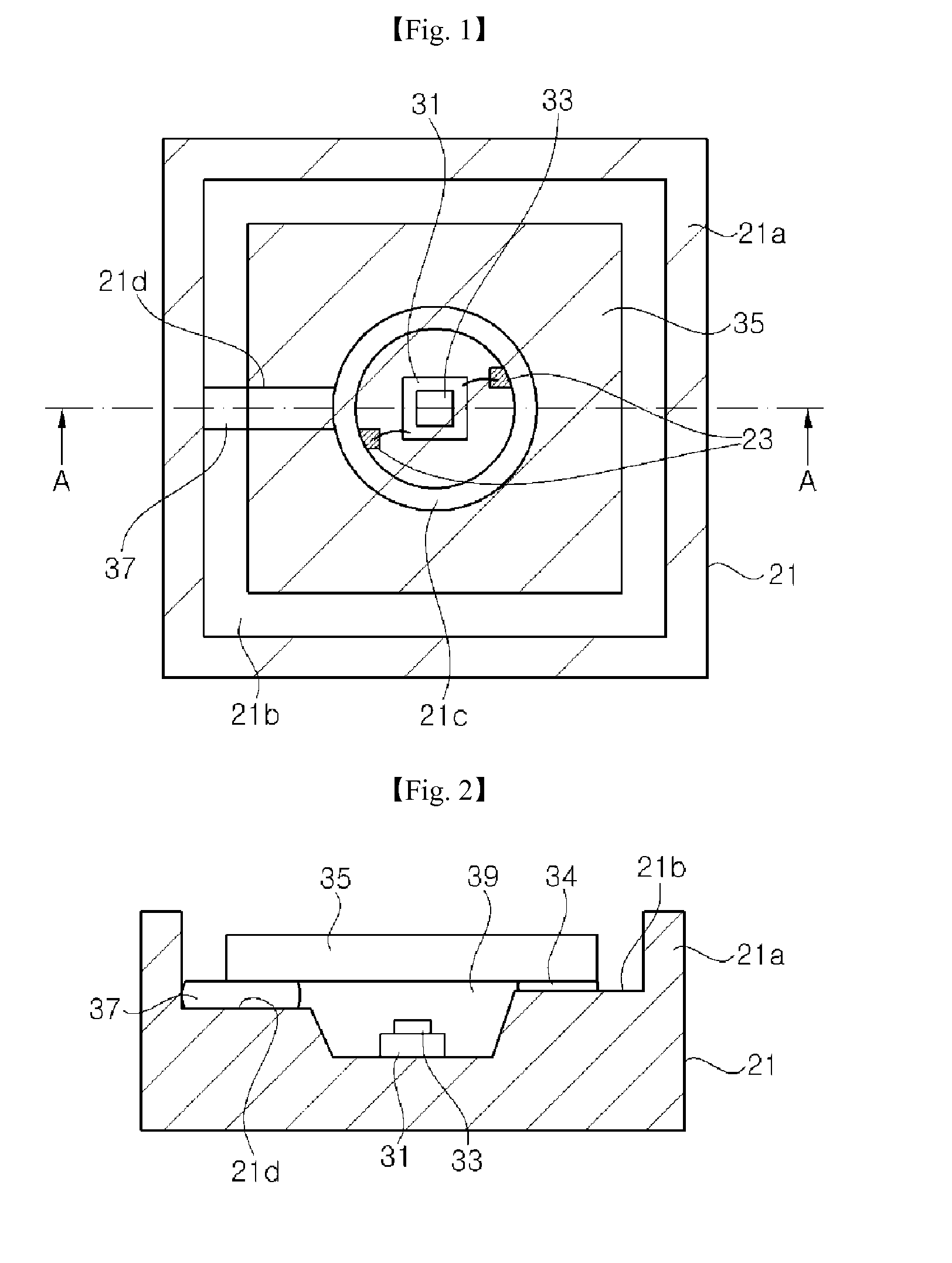
[0023]FIG. 1 is a plan view of a light emitting diode package according to one embodiment of the present invention and FIG. 2 is a cross-sectional view taken along line A-A of FIG. 1.

[0024]Referring to FIG. 1 and FIG. 2, a light emitting diode package according to one embodiment of the invention inc...


PUM


Abstract

Disclosed are a light-emitting diode package and a method for manufacturing same. The method for manufacturing a light-emitting diode package comprises: preparing a package main body having a cavity and an air vent passageway which extends from the cavity; installing a light-emitting diode inside the cavity of the package main body; attaching a transparent member by means of an adhesive so as to cover the upper part of the cavity; and blocking the air vent passageway by forming a sealing member. As the air vent passageway is blocked after the transparent member is attached, the transparent member may be prevented from peeling off from the air pressure inside the cavity.

Description

CROSS-REFERENCE TO RELATED APPLICATIONS[0001]This application is the National Stage of International Application PCT / KR2012 / 008153, filed on Oct. 9, 2012, and claims priority from and the benefit of Korean Patent Application No.10-2011-0112025, filed on Oct. 31, 2011, which are hereby incorporated by reference for all purposes as if fully set forth herein.BACKGROUND OF THE INVENTION[0002]1. Field[0003]The present invention relates to a light emitting diode package and, more particularly, to a UV light emitting diode package and a method of fabricating the same.[0004]2. Discussion of the Background[0005]Gallium nitride-based light emitting diodes are widely used for display devices and backlight units. In addition, with low power consumption and long lifespan as compared is with existing incandescent lamps or fluorescent lamps, applications of light emitting diodes have expanded to general lighting by replacing existing incandescent lamps, fluorescent lamps, and the like. Recently, l...

Claims


Application Information

Patent Timeline
IPC IPC(8): H01L33/58
CPCH01L33/486H01L33/58H01L2933/0058H01L2924/0002H01L2924/00H01L2933/0033H01L33/48
Inventor JUNG, HEE CHEULCHAE, JUNG HYEJANG, BO RAM IPARK, JUN YONGSUH, DAE WOONG
Owner SEOUL VIOSYS CO LTD
Why Eureka
Try Eureka