Battery-State Monitoring System

a storage battery and monitoring system technology, applied in instruments, greenhouse gas reduction, transportation and packaging, etc., can solve the problems of accelerating the degradation of storage batteries, affecting the service life of storage batteries, and human inability to take complete control, so as to reduce the variation of voltage, reduce the effect of overdischarge or overcharge of each storage battery

Inactive Publication Date: 2014-09-25
HITACHI CHEM CO LTD
View PDF5 Cites 40 Cited by
  • Summary
  • Abstract
  • Description
  • Claims
  • Application Information

AI Technical Summary

Benefits of technology

[0022]The effects obtained by typical embodiments of the invention disclosed in the present application will be briefly described below.
[0023]According to a typical embodiment of the present invention, it is possible to provide a battery-state monitoring system capable of highly precisely and efficiently estimating the state and service life of each storage battery while suppressing the variations in voltage between storage batteries in a large-scale power supply system having a plurality of storage batteries which are charged with power generated by utilizing natural energy and are constantly connected to an equipment. Also, according to a typical embodiment of the present invention, it is possible to control each storage battery so as to operate in a given partial state of charge, and thus possible to prevent each storage battery from being overdischarged or overcharged.BRIEF DESCRIPTIONS OF THE DRAWINGS
[0024]FIG. 1 is a schematic diagram of a configuration example of a battery-state monitoring system according to one embodiment of the present invention;
[0025]FIG. 2 is a schematic diagram of a configuration example of a prime monitoring device according to the one embodiment of the present invention;
[0026]FIG. 3 is a schematic diagram of a configuration example of a state measuring device (end device) according to the one embodiment of the present invention;
[0027]FIG. 4 is a flowchart schematically showing an example of a process of controlling measurement timing of voltage and temperature by the state measuring device (end device) in the one embodiment of the present invention;

Problems solved by technology

However, in the case of utilizing natural energy, the energy source is natural phenomena such as sunshine and wind conditions, and the human cannot take complete control thereof.
However, in the case of the solar battery, for example, when the sunshine in the daytime is abundant and the storage battery is kept supplied with surplus power, the storage battery may be overcharged, and it accelerates the degradation of the storage battery.
Meanwhile, when sunshine is scarce, since the storage battery has to keep supplying power to the load, the storage battery may be overdischarged, and it also accelerates the degradation of the storage battery.

Method used


Image

  • Battery-State Monitoring System
  • Battery-State Monitoring System
  • Battery-State Monitoring System

Examples


Embodiment Construction

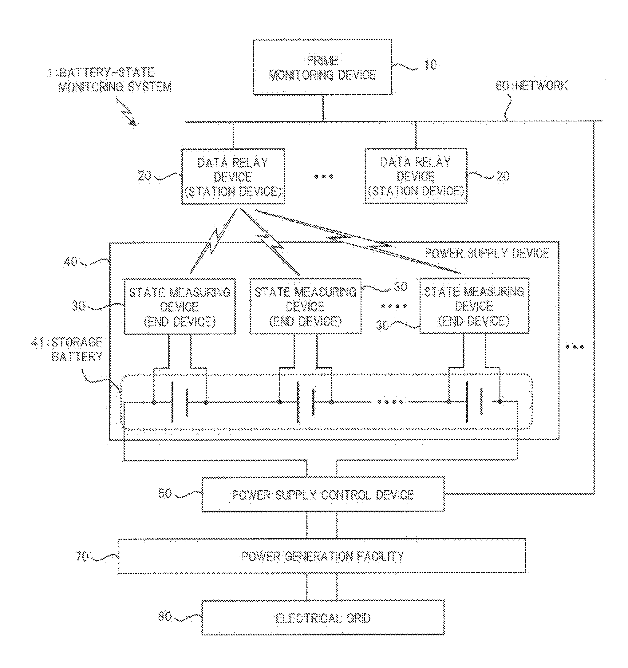
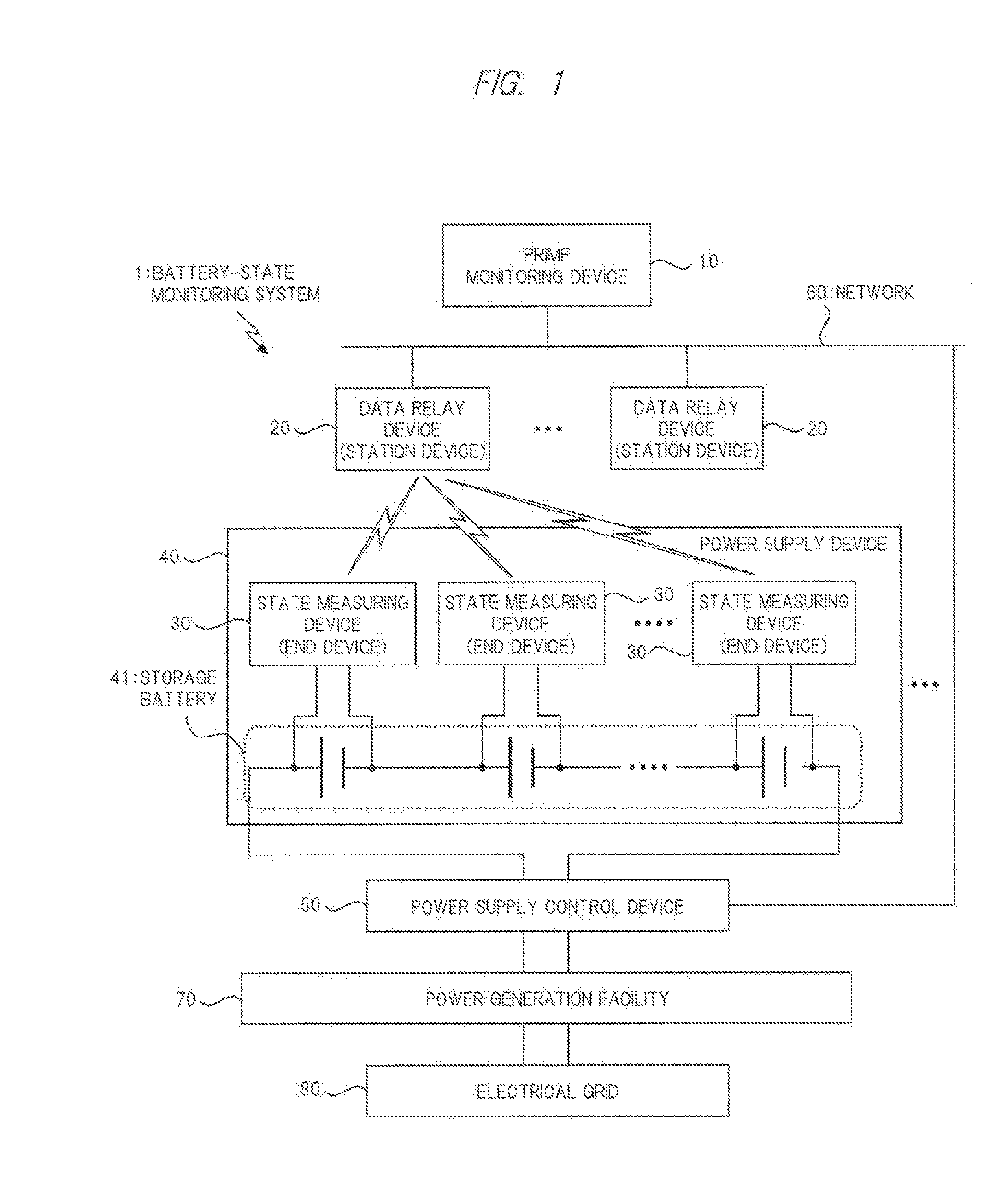
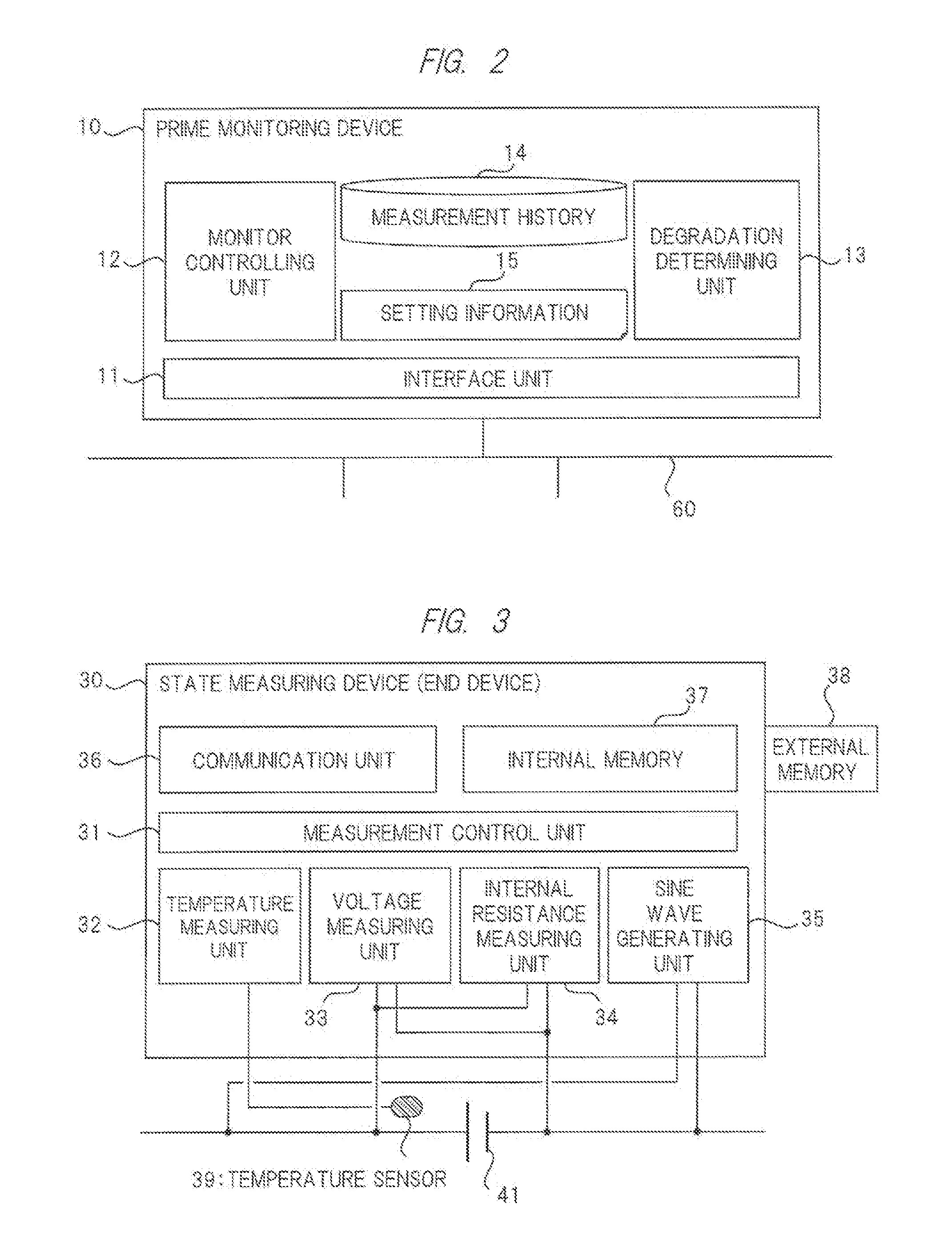
[0030]Hereinafter, embodiments of the present invention will be described in detail with reference to the accompanying drawings. Note that components having the same function are denoted by the same reference symbols throughout the drawings for describing the embodiments, and the repetitive description thereof will be omitted in principle.

[0031]

[0032]As described above, a power supply system composed by combining a power generator such as a solar battery and a wind power generator and a storage battery has been used as a self-contained power supply utilizing natural energy or a power leveling mechanism. In the power supply system like this, power generated by natural energy is supplied to a load, but the power generation amount changes due to a change in the natural environment, which leads to shortage or excess in the power supply to the load. For this reason, fluctuations of the power generation amount and power supply to the load are absorbed by using the storage battery, and pow...


PUM


Abstract

A battery-state monitoring system for precisely and efficiently estimating the state and service life of each of a plurality of storage batteries while suppressing variations in voltage between the batteries in a large-scale power-supply system that is provided with the storage batteries charged with power generated by utilizing natural energy is provided. The system includes a power supply control device that detects a current in each storage battery, an end device that measures temperature, voltage, and internal resistance of each battery, the internal resistance being measured by using at least two or more kinds of frequencies, and a prime monitoring device that acquires measurement data from the end device corresponding to each battery and issues an instruction related to an operation to the power supply control device and the end device. The prime monitoring device estimates degradation of each battery based on one or more of temperature, voltage, internal resistance.

Description

TECHNICAL FIELD[0001]The present invention relates to a technique for monitoring the state of a storage battery, and particularly relates to a technique effectively applied to a battery-state monitoring system which monitors and estimates the state of a storage battery which is used in a large-scale power supply system combined with a power generation facility utilizing natural energy.BACKGROUND ART[0002]In recent years, a power supply system composed by combining, for example, a power generator or charger utilizing natural energy such as a solar battery and a wind power generator, a storage battery, and a control system for these has been used as a self-contained power supply or a power leveling mechanism thereof. Such a power supply system is used as a single independent power supply and is sometimes operated while inputting and outputting power to / from the ordinary commercial power source in a so-called grid connection. Recently, like the so-called smart grid, the efficiency of t...

Claims


Application Information

Patent Timeline
Patent Type & Authority Applications(United States)
IPC IPC(8): G01R31/36H02J7/00
CPCG01R31/3624H02J7/0021G01R31/3679G01R31/3662G01R31/389G01R31/392G01R31/3842G01R31/371G01R31/396Y02E10/50Y02E70/30G01R31/382
Inventor MUKAITANI, ICHIROKOFUSE, TAKASHIKANOH, MITSUYOSHIMIZUSUGI, SHINYASHIBATA, YASUHIRO
Owner HITACHI CHEM CO LTD
Why Eureka
Try Eureka