
Liquid ejection device and printing device

a printing device and liquid ejection technology, applied in printing, printed circuit details, cross-talk/noise/interference reduction, etc., can solve the problems of increasing the wire impedance, reducing the power efficiency, and emi noise, and achieve good print quality

Active Publication Date: 2014-09-25
COLUMBIA PEAK VENTURES LLC
View PDF6 Cites 14 Cited by
  • Summary
  • Abstract
  • Description
  • Claims
  • Application Information

AI Technical Summary

Benefits of technology

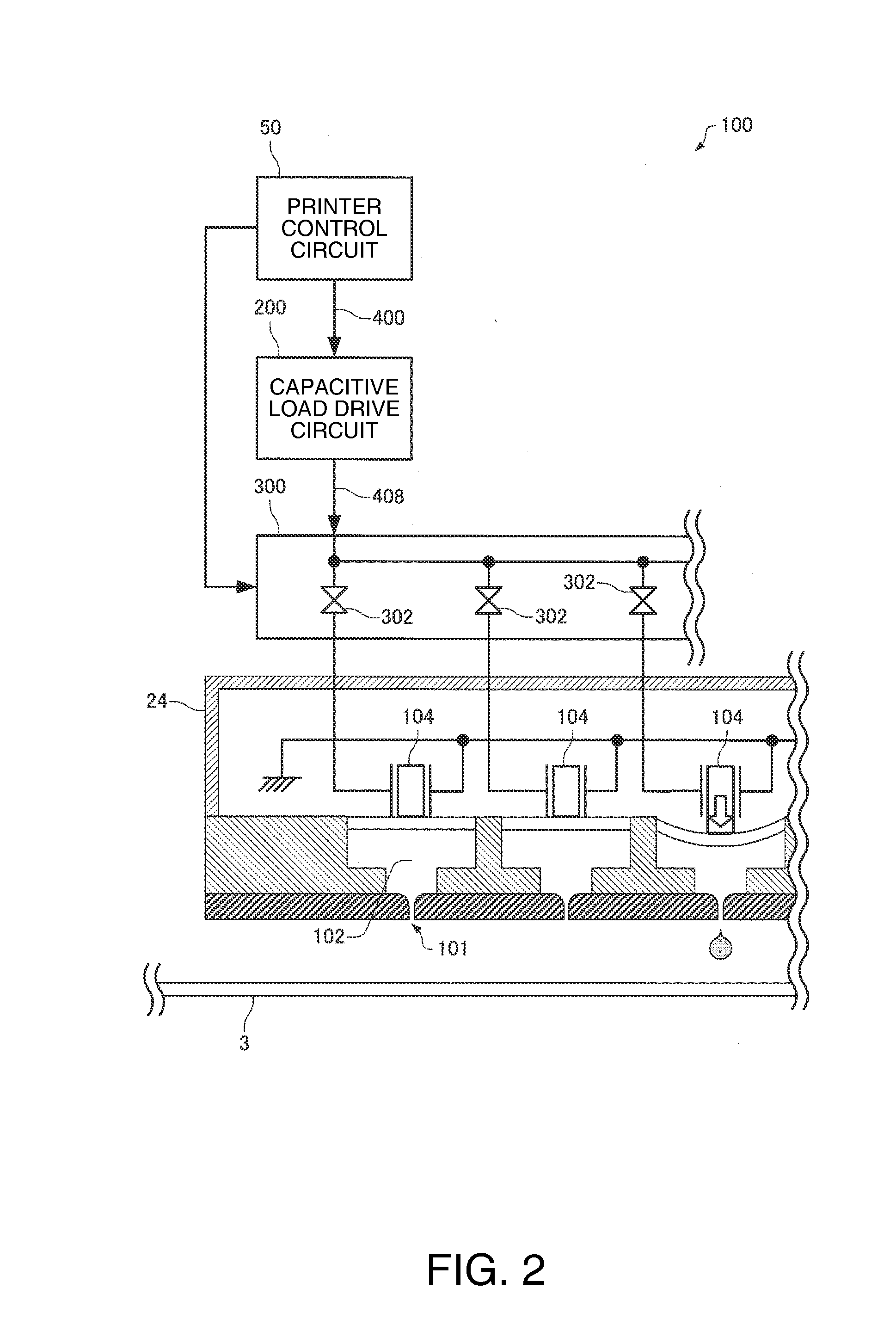
This patent describes a liquid ejection device that reduces output voltage ringing and improves printing quality. This is achieved by arranging a third via conductor in a way that prevents interference with other wires, which reduces wire impedance in a loop containing the first and second transistors and a capacitor. Ultimately, this results in an accurate and efficient device for discharging liquid.

Problems solved by technology

In this case, when an analog drive waveform signal is power-amplified in an analog manner to directly generate an analog drive signal, power efficiency is reduced because a large power loss occurs.
In inkjet printers, the occurrence of ringing leads to the occurrence of EMI noise.
As a result, the discharge amount of ink varies, which is obstructive to an improvement in print quality.
In a multilayer wiring board shown in FIGS. 1 and 2 of Patent Document 1, a wire has to be routed around via conductors, which is a cause of increasing the wire impedance of the loop formed of the two transistors and the bypass capacitor that constitute the switching circuit.
For this reason, when the multilayer wiring board disclosed in Patent Document 1 is used for a printing device or the like, there are limitations to suppress ringing, that is, to improve print quality.

Method used


Image

  • Liquid ejection device and printing device
  • Liquid ejection device and printing device
  • Liquid ejection device and printing device

Examples


Embodiment Construction

[0035]Hereinafter, a preferred embodiment of the invention will be described in detail with reference to the drawings. The drawings used herein are for purposes of description. The embodiment described below does not unduly limit the contents of the invention set forth in the appended claims. Moreover, not all of the configurations described below are essential components of the invention.

[0036]The embodiment of the invention will be described below in the following order.

[0037]1. Configuration example of printing device and liquid ejection device

[0038]2. Circuit configuration of capacitive load drive circuit

[0039]3. Arrangement example of switching circuit

[0040]4. Modified example of arrangement example of switching circuit

[0041]5. Medical device

1. Configuration Example of Printing Device and Liquid Ejection Device

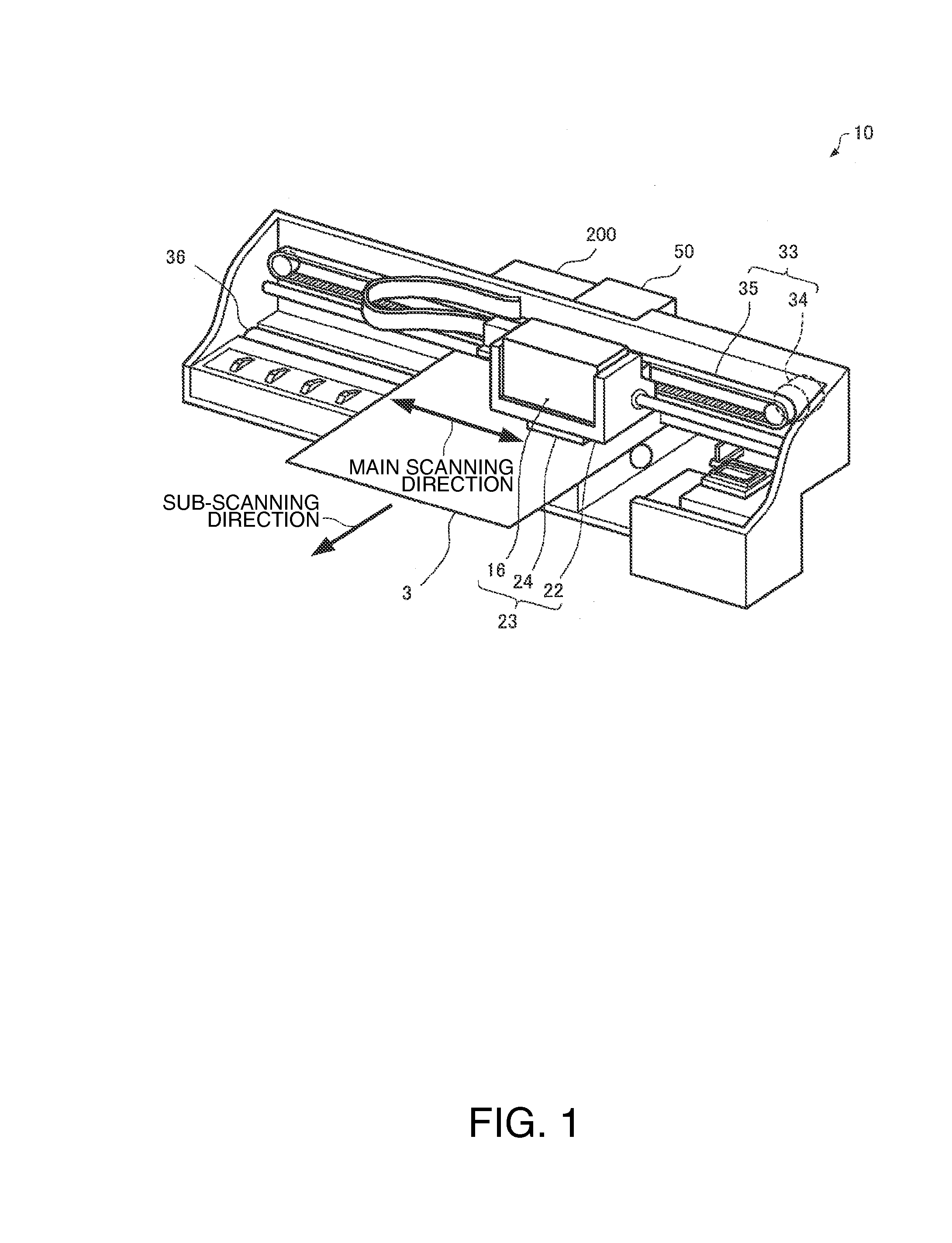
[0042]FIG. 1 is an explanatory view showing a configuration example of an inkjet printer 10 as an example of a printing device. The inkjet printer 10 shown in FIG. 1 incl...


PUM


Abstract

A liquid ejection device includes a switching circuit. The switching circuit includes: a multilayer wiring board including a first wiring layer and a second wiring layer; a first transistor and a second transistor mounted on the first wiring layer side of the multilayer wiring board; and a capacitor mounted on the second wiring layer side of the multilayer wiring board. When the multilayer wiring board is viewed in a plan view, a third via conductor is arranged in an area not overlapping a straight-line path connecting a source electrode of the first transistor with a drain electrode of the second transistor in a second wire.

Description

[0001]This application claims the benefit of Japanese Patent Application No. 2013-62926, filed on Mar. 25, 2013. The content of the aforementioned application is incorporated herein by reference in its entirety.BACKGROUND[0002]1. Technical Field[0003]The present invention relates to a liquid ejection device, a printing device, and the like.[0004]2. Related Art[0005]Like an ejection head mounted on an inkjet printer, there are many actuators composed of a capacitive load such as a piezoelectric element. For driving the actuator as a capacitive load, a drive signal at a certain level of power is needed. Therefore, the drive signal is generated by power-amplifying a drive waveform signal as the source of the drive signal. In this case, when an analog drive waveform signal is power-amplified in an analog manner to directly generate an analog drive signal, power efficiency is reduced because a large power loss occurs. Therefore, a technique of performing power amplification using a so-ca...

Claims


Application Information

Patent Timeline
Patent Type & Authority Applications(United States)
IPC IPC(8): B41J2/045
CPCB41J2/0455B41J2/04581B41J2/04541H05K1/0231
Inventor OSHIMA, ATSUSHIIDE, NORITAKA
Owner COLUMBIA PEAK VENTURES LLC
Learn More