Sparse and ultra-sparse partial resonant converters

Active Publication Date: 2014-09-25
TEXAS A&M UNIVERSITY
View PDF9 Cites 6 Cited by
  • Summary
  • Abstract
  • Description
  • Claims
  • Application Information

AI Technical Summary

Benefits of technology

[0024]A novel topology for transforming electric power is described herein. The input and output of the sparse or ultra-sparse partial resonant converter can be either AC (single-phase or multi-phase) or DC. The sparse or ultra-sparse partial resonant converter contains fewer switches as compared to the prior art (e.g., 24), which results in

Problems solved by technology

Typical converters require numerous switches and are therefore complicated and expensive.
However, partial resona

Method used


Image

  • Sparse and ultra-sparse partial resonant converters
  • Sparse and ultra-sparse partial resonant converters
  • Sparse and ultra-sparse partial resonant converters

Examples


Embodiment Construction

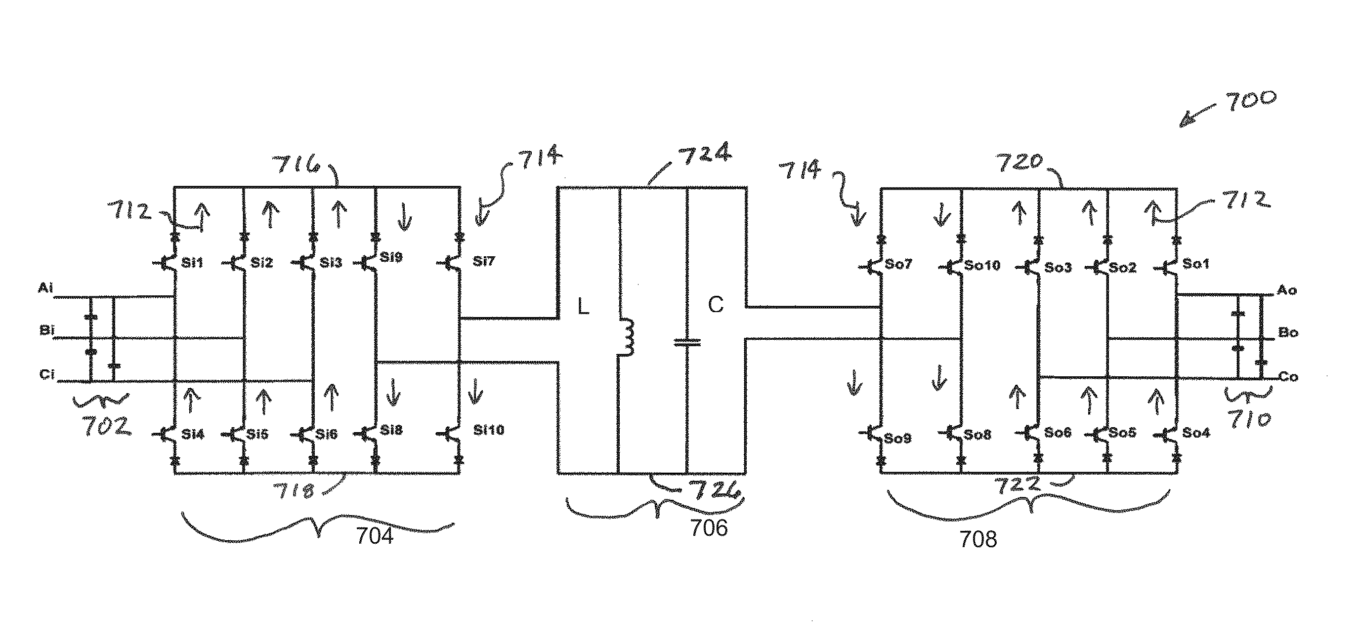
[0048]The teachings of the disclosure recognize that less complex partial resonant converters are desired for applications that do not need bi-directional power flow. Such applications may include, for example, converters that interface a power grid and wind-driven or wave-driven generators. The included figures illustrate embodiments of ultra-sparse partial resonant converters that include a reduced number of switches from typical partial resonant converters.

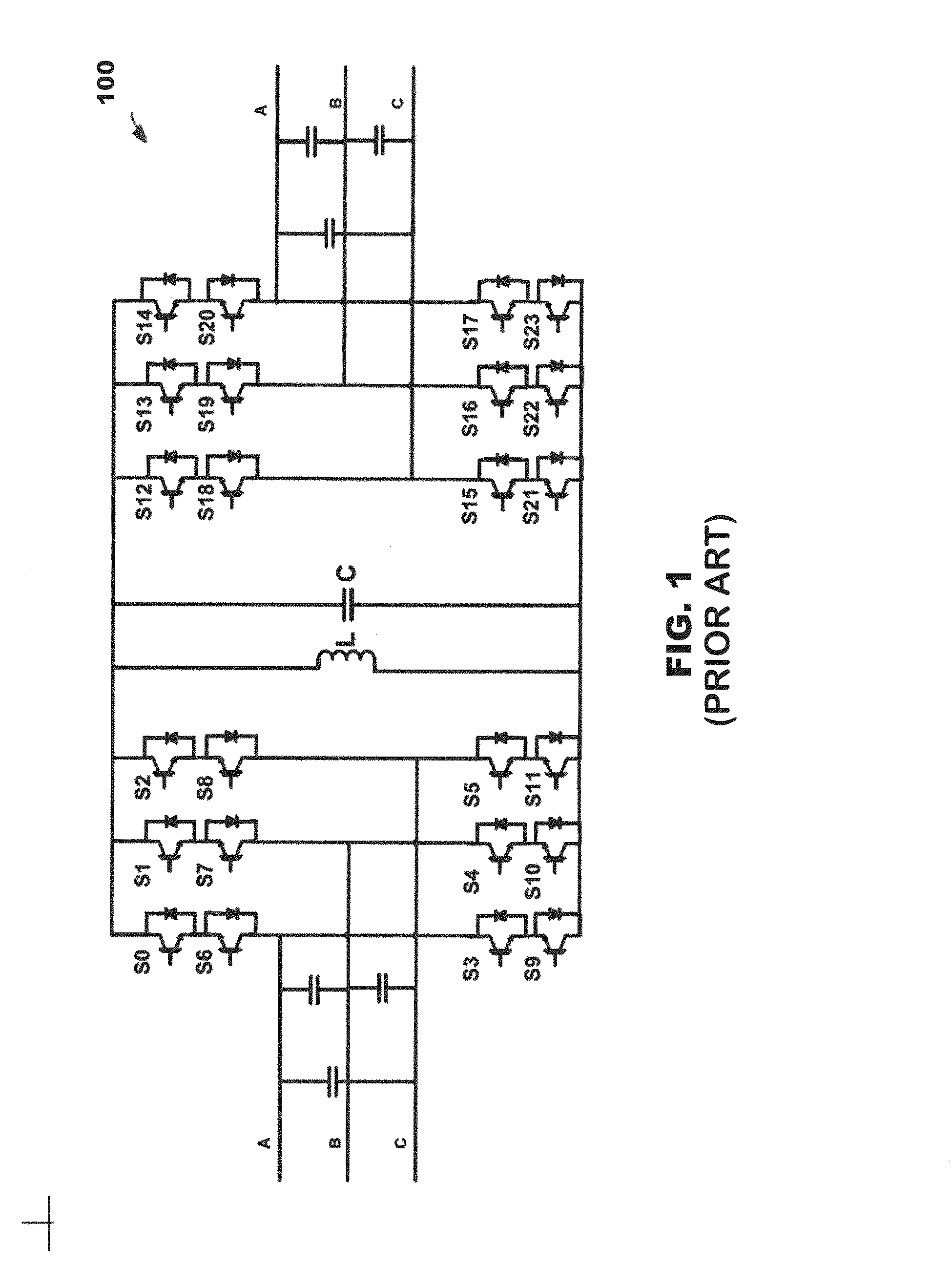
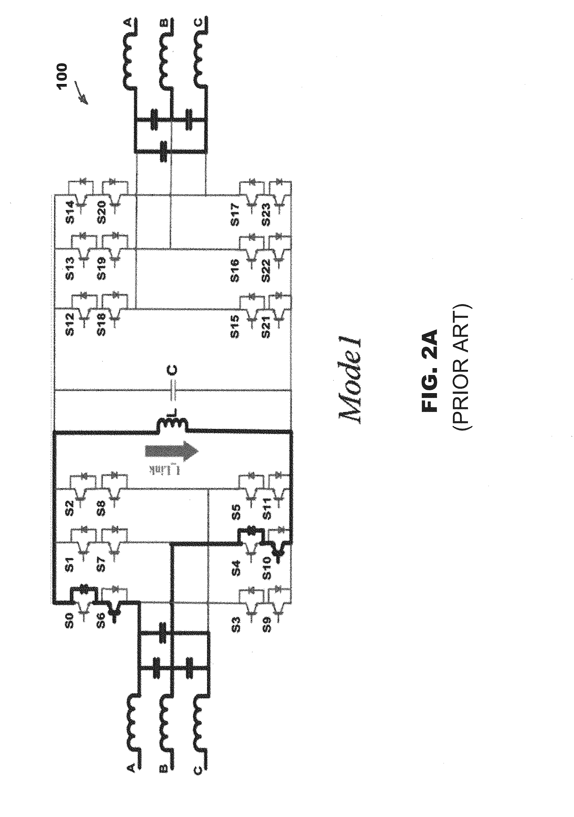
[0049]In general, an ultra-sparse partial resonant converter includes a configuration that reduces the number of switches from 24 in a typical three-phase AC-AC partial resonant converter to 20 in the case of a sparse resonant converter and 16 in the case of an ultra-sparse resonant converter. The ultra-sparse partial resonant converter is especially useful for applications that do not need bi-directional power flow. Among these applications are converters interfacing a power grid and wind-driven or wave-driven generators.

[0050...


PUM


Abstract

The AC portion of the input of the ultra-sparse partial resonant power converter contains three pairs of forward-conducting-bidirectional-blocking switches connected in a first direction, and two pairs of forward-conducting-forward-blocking devices connected in a second direction to the three pairs of forward-conducting-bidirectional-blocking switches. The second direction is opposite to the first direction. The AC portion of the output of the ultra-sparse partial resonant power converter contains three pairs of forward-conducting-bidirectional-blocking switches connected in a first direction, and two pairs of forward-conducting-reverse-blocking devices connected in a second direction to the three pairs of forward-conducting-bidirectional-blocking switches. The forward-conducting-reverse-blocking devices can be switches or diodes.

Description

CROSS REFERENCE TO RELATED APPLICATIONS[0001]This application claims priority to and is: (1) a continuation-in-part application of U.S. patent application Ser. No. 13 / 486,627 filed on Jun. 1, 2012, which is a non-provisional application of U.S. Provisional Patent Application Ser. No. 61 / 493,210 filed on Jun. 3, 2011; and (2) a non-provisional application of U.S. Provisional Patent Application Ser. No. 61 / 831,446 filed on Jun. 5, 2013. The entire contents of the foregoing patent applications are hereby incorporated by reference.STATEMENT REGARDING FEDERALLY SPONSORED RESEARCH OR DEVELOPMENT[0002]Not Applicable.NAMES OF THE PARTIES TO A JOINT RESEARCH AGREEMENT[0003]Not Applicable.INCORPORATION-BY-REFERENCE OF MATERIAL SUBMITTED ON A COMPACT DISC OR AS A TEXT FILE VIA THE OFFICE ELECTRONIC FILING SYSTEM (EFS-WEB)[0004]Not Applicable.FIELD OF THE INVENTION[0005]This disclosure relates in general to power converters and more particularly to sparse and ultra-sparse partial resonant conve...

Claims


Application Information

Patent Timeline
IPC IPC(8): H02M5/458
CPCH02M5/458H02M5/4585Y02B70/145Y02B70/10Y02P80/10
Inventor TOLLYAT, HAMID A.AMIRABADI, MAHSHID
Owner TEXAS A&M UNIVERSITY
Why Eureka
Try Eureka