Receptacle cage, receptacle assembly, and transceiver module assembly
- Summary
- Abstract
- Description
- Claims
- Application Information
AI Technical Summary
Benefits of technology
Problems solved by technology
Method used
Image
Examples
Embodiment Construction
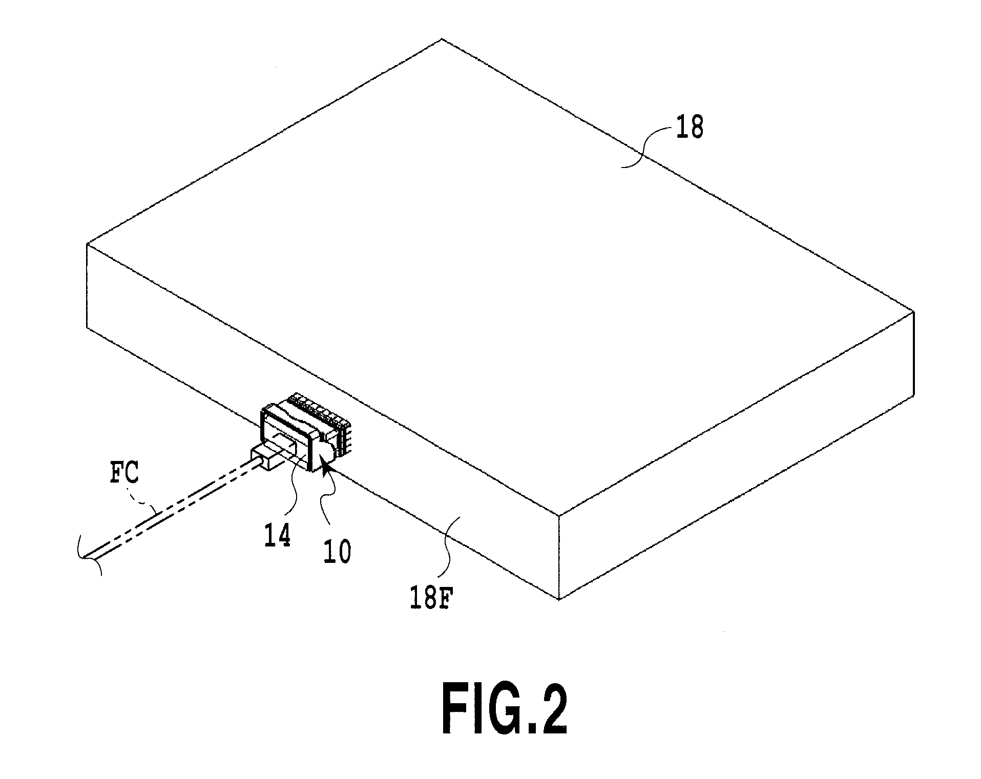
[0045]FIG. 2 shows an example of a transceiver module assembly according to the present invention together with a housing 18 for embedding the assembly.
[0046]An end portion of an optical module 14 of a transceiver module assembly 10 to be described later protrudes out of an operating side end surface 18F of the housing 18. An optical connector, to which one end of an optical cable FC is connected, is connected to a port provided at the end portion of the optical module 14. Another end of the optical cable FC is connected to an optical connector of another housing which constitutes an unillustrated communication system.
[0047]As shown in FIG. 3, the housing 18 configured to define an enclosed space inside contains a printed wiring board 16 on which the transceiver module assembly 10 is mounted. In FIG. 3, one transceiver module assembly 10 is mounted on one printed wiring board 16. However, the present invention is not limited only to this configuration and multiple transceiver module...
PUM
 Abstract
Description
Claims
Application Information
 - R&D
- Intellectual Property
- Life Sciences
- Materials
- Tech Scout
- Unparalleled Data Quality
- Higher Quality Content
- 60% Fewer Hallucinations
Browse by: Latest US Patents, China's latest patents, Technical Efficacy Thesaurus, Application Domain, Technology Topic, Popular Technical Reports.
© 2025 PatSnap. All rights reserved.Legal|Privacy policy|Modern Slavery Act Transparency Statement|Sitemap|About US| Contact US: help@patsnap.com


