Cooling system for spot welding device

Inactive Publication Date: 2014-10-02
HYUNDAI MOTOR CO LTD
View PDF3 Cites 2 Cited by
  • Summary
  • Abstract
  • Description
  • Claims
  • Application Information

AI Technical Summary

Benefits of technology

[0031]Therefore, since coolant utilities such as a coolant pump and a coolant pipe of the related art can be removed in an exemplary embodiment

Problems solved by technology

However, since the water-cooled cooling system of the spot welding device has a structure that circulates a coolant to the heating parts of the spot welding device, there is

Method used


Image

  • Cooling system for spot welding device
  • Cooling system for spot welding device
  • Cooling system for spot welding device

Examples


Embodiment Construction

[0039]Reference will now be made in detail to various embodiments of the present invention(s), examples of which are illustrated in the accompanying drawings and described below. While the invention(s) will be described in conjunction with exemplary embodiments, it will be understood that the present description is not intended to limit the invention(s) to those exemplary embodiments. On the contrary, the invention(s) is / are intended to cover not only the exemplary embodiments, but also various alternatives, modifications, equivalents and other embodiments, which may be included within the spirit and scope of the invention as defined by the appended claims.

[0040]The present invention will be described more fully hereinafter with reference to the accompanying drawings, in which exemplary embodiments of the invention are shown. As those skilled in the art would realize, the described embodiments may be modified in various different ways, all without departing from the spirit or scope ...


PUM

PropertyMeasurementUnit
Temperatureaaaaaaaaaa
Flow rateaaaaaaaaaa
Energyaaaaaaaaaa

Abstract

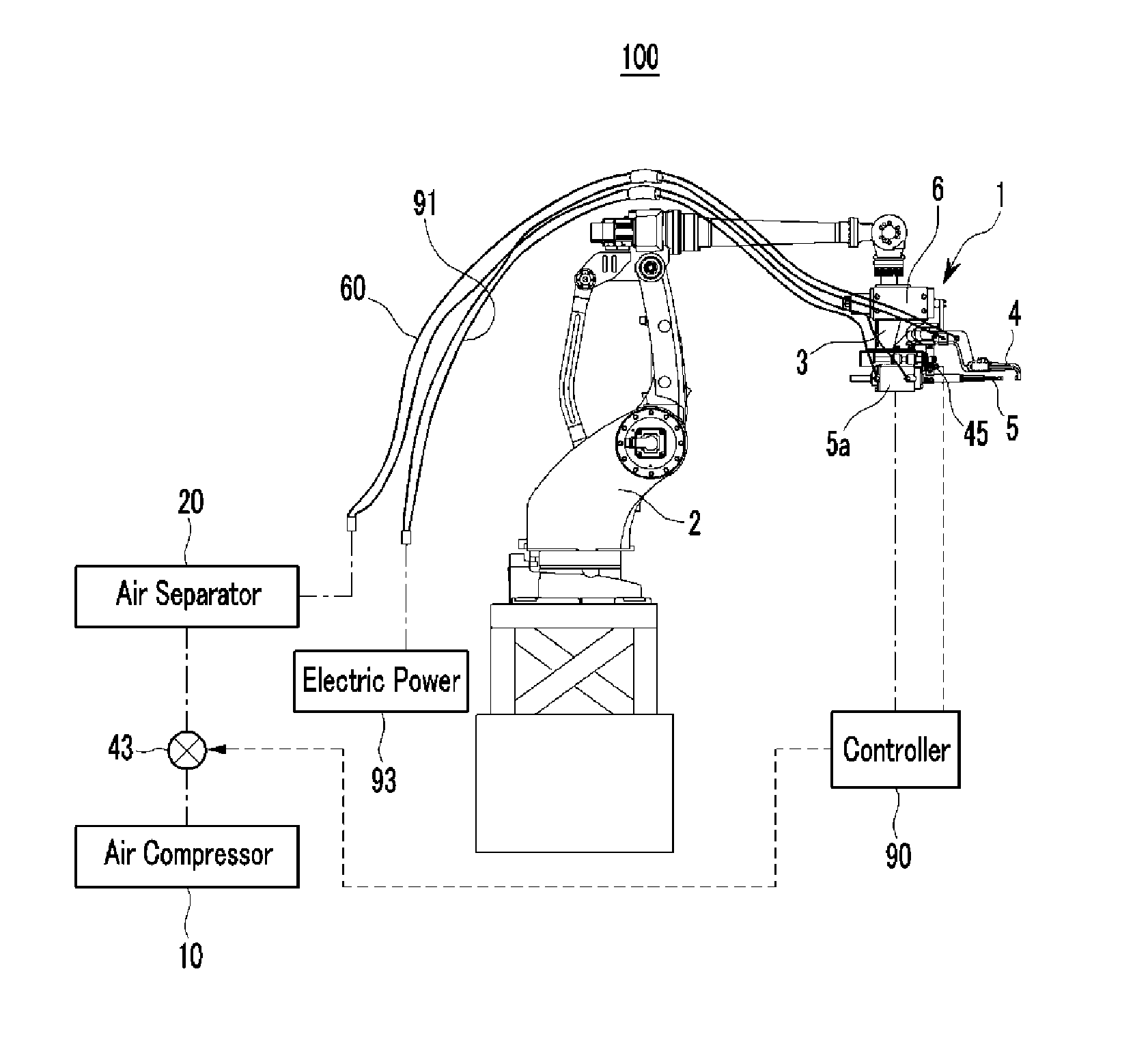
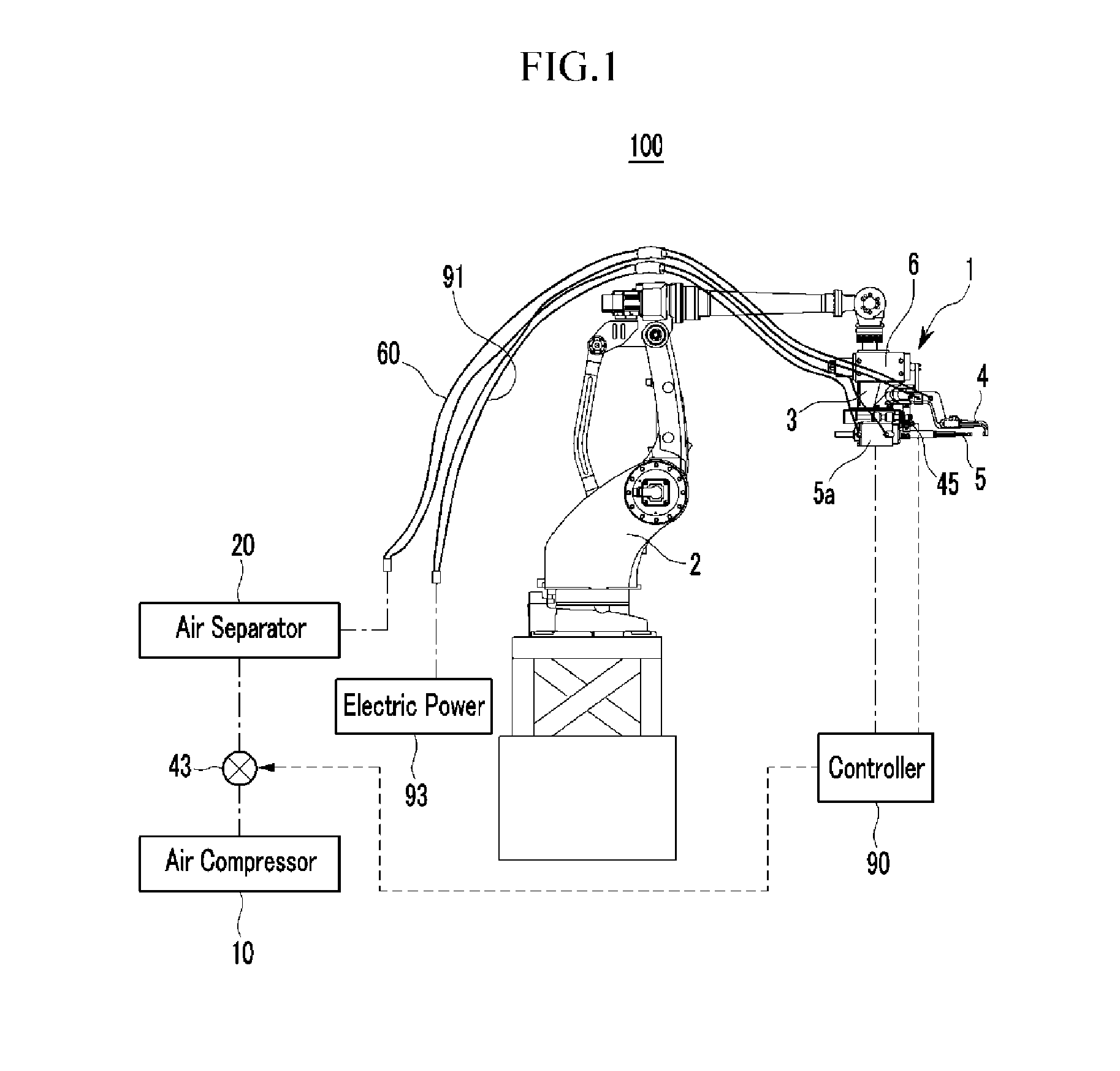
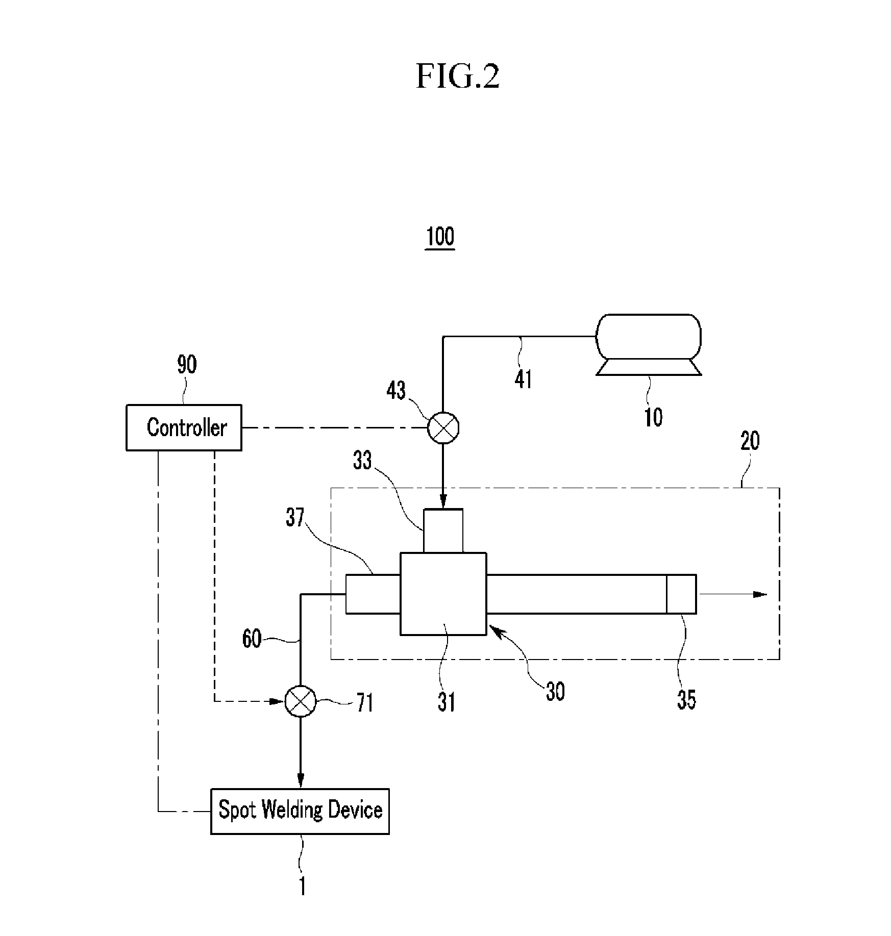
A cooling system for a spot welding device which cools heating parts of a spot welding device including two electrodes, a gun body, and a transformer, may include an air compressor, an air separator connected with the air compressor and separating compressed air supplied from the air compressor into hot air and cooling air, and a connection line supplying the cooling air separated by the air separator to a heating part of the spot welding device.

Description

CROSS-REFERENCE TO RELATED APPLICATION[0001]The present application claims priority to Korean Patent Application No. 10-2013-0032188 filed on Mar. 26, 2013, the entire contents of which is incorporated herein for all purposes by this reference.BACKGROUND OF THE INVENTION[0002]1. Field of the Invention[0003]An exemplary embodiment of the present invention relates to a cooling system for a spot welding device. More particularly, the present invention relates to a cooling system for a spot welding device which can cool a heating portion of a spot welding device with cooling air.[0004]2. Description of Related Art[0005]In general, several parts such as panels are bonded by spot welding in the assembly line of a vehicle body factory. Spot welding is a welding method of bonding objects to weld, using electric resistance by applying electricity and pressure to the object to weld which overlap.[0006]A spot welding device is used for the spot welding and basically includes a fixed electrode ...

Claims


Application Information

Patent Timeline
IPC IPC(8): B23K37/00
CPCB23K37/003B23K11/11B23K11/36B23K2101/006B23K11/3018B23K11/3054
Inventor RYU, HYUN JUNGKIM, DONG MYONG
Owner HYUNDAI MOTOR CO LTD
Why Eureka
Try Eureka