Tread including at least one wavy groove, and method for producing same

a groove and groove technology, applied in the field of treads, can solve the problems of rubber breakage, reduced service life of tires, and broken grooves at the bottom of certain grooves

Active Publication Date: 2014-10-02
MICHELIN & CO CIE GEN DES ESTAB MICHELIN
View PDF10 Cites 14 Cited by
  • Summary
  • Abstract
  • Description
  • Claims
  • Application Information

AI Technical Summary

Benefits of technology

[0022]Disclosed herein is a tread for a tire intended to be fitted to a heavy goods vehicle and which, by the use of a type of tread pattern, allows a significant and simultaneous improvement in this tread of: the wear performance, the rolling resistance performance, the wet roadway grip performance, the resistance to mechanical attack notably to the bottoms of the grooves near the lateral edges.

Problems solved by technology

While grooves, or more generally, cavities, are essential to draining water away, the resulting reduction in surface area of material may have an appreciable effect on the wear rate performance of a tread and therefore reduce the service life of the tire as the result of an increase in the wear rate.
It is also found that these grooves which are formed to have a working depth equal to the height of tread to be worn away may be the cause of endurance problems.
Under certain driving conditions, foreign objects such as stones may become lodged in these grooves and attack the bottoms of these grooves and cause breakages to appear in the rubber.
It has also been observed that manoeuvres involving mounting and descending from various obstacles can cause breakages at the bottoms of certain grooves, notably those situated near the lateral edges of the tread.
This reduction in stiffness, in the case of the presence of grooves, leads to an increase in deformation and generates a reduction in the wear performance of the tread: greater wear for a set distance covered is observed (which corresponds to an increase in the tread wear rate).
Moreover, an increase in the rolling resistance and therefore in the fuel consumption of vehicles equipped with such tires is noted, this being the result of an increase in hysteresis losses which are associated with the deformation cycles of the material of which the tread is made.

Method used


Image

  • Tread including at least one wavy groove, and method for producing same
  • Tread including at least one wavy groove, and method for producing same
  • Tread including at least one wavy groove, and method for producing same

Examples


Embodiment Construction

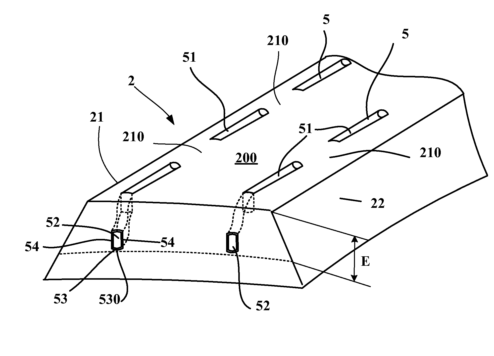
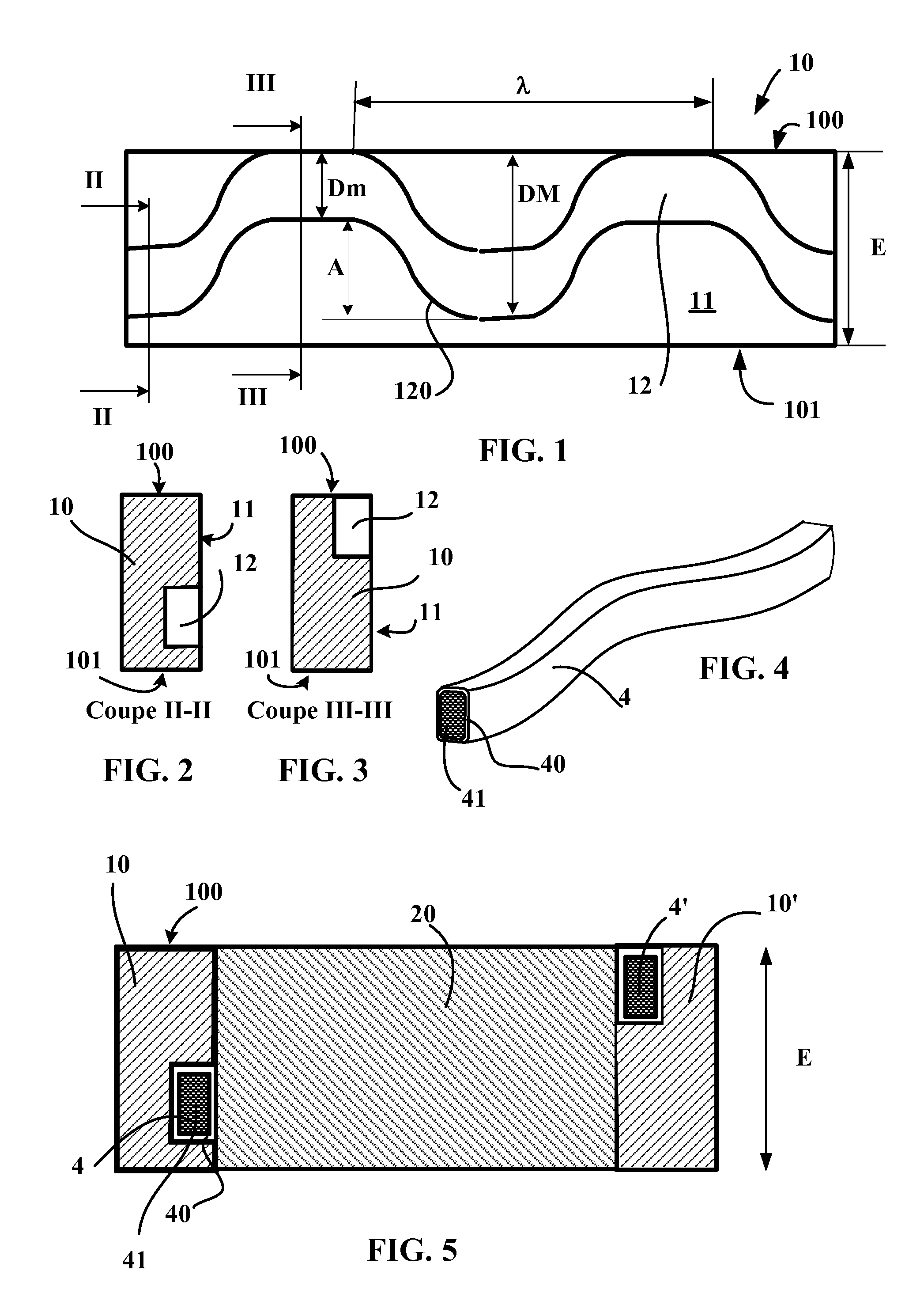
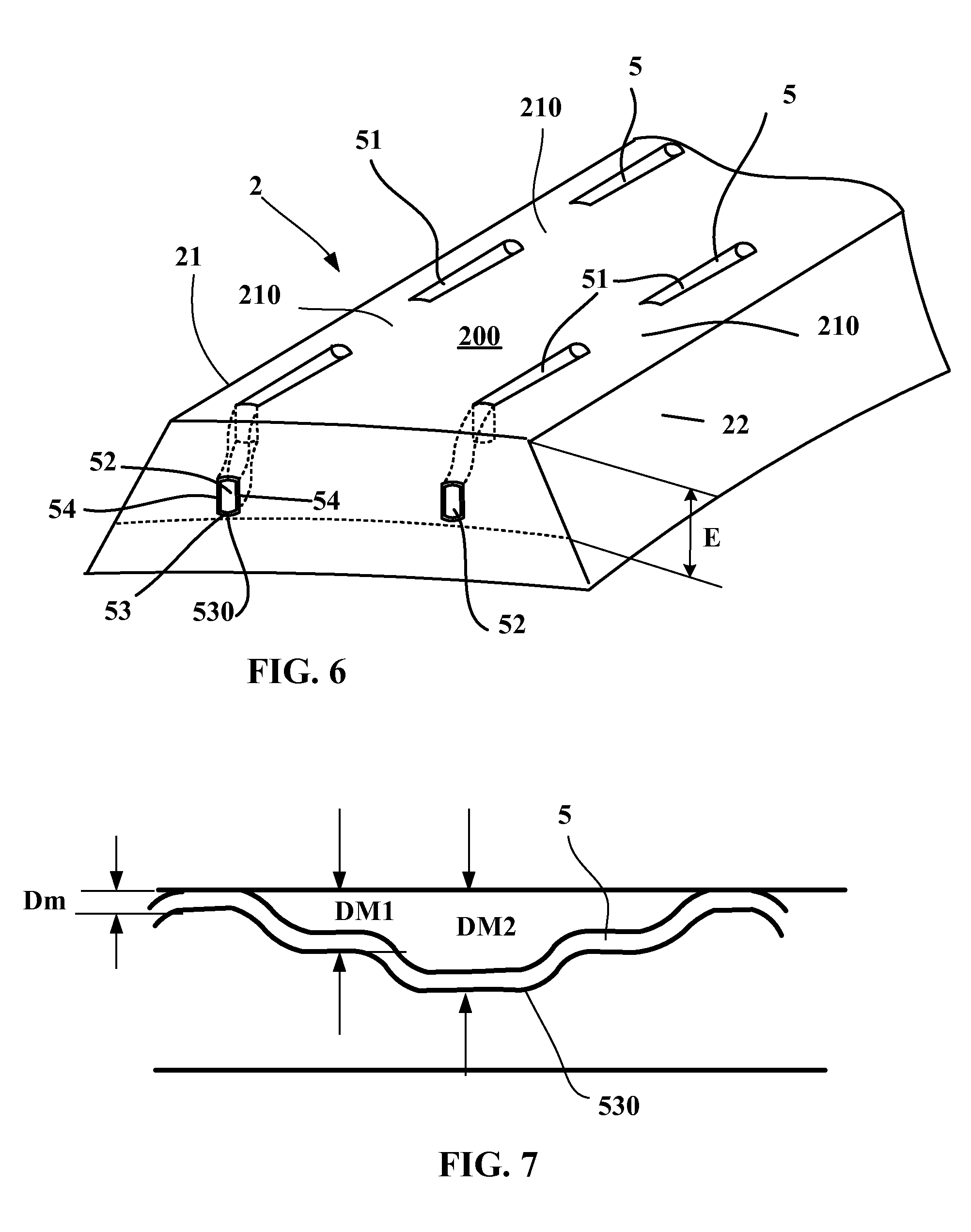
[0076]FIGS. 1 to 5 show the steps involved in producing a tread according to the invention.

[0077]FIG. 1 shows a lateral surface 11 of an unvulcanized band of rubber 10 that has an external surface 100 intended to become part of a surface of a tread after vulcanizing and molding and an internal surface 101 intended to be placed on a green tire. This band of rubber has—measured between the external 100 and internal 101 surfaces, a height E corresponding to the thickness of the tread. Formed on the lateral surface 11 of this band of rubber 10 is a groove 12 following a wavy line in the height E of the tread.

[0078]This groove 12 is appropriately sized to accept an insert 4 like the one shown in example in FIG. 4. This groove 12 has a wavy shape and is continuous in the main direction of the band of rubber. This groove 12 comprises a bottom line 120 (line connecting the points on the bottom which are furthest towards the inside) which undulates between a minimum distance Dm and a maximum...


PUM

PropertyMeasurementUnit
depthaaaaaaaaaa
depthaaaaaaaaaa
groove depthaaaaaaaaaa

Abstract

Tire for a heavy goods vehicle comprising a tread of total thickness E and total volume V, having a tread surface intended to come into contact with a roadway, at least one cavity or groove that is continuous in a main direction, and delimited by side walls connected by a bottom, a cross section, the points furthest towards the inside of the bottom of each cavity defining a bottom line, wherein each cavity or groove comprises a plurality of open sections open onto the tread surface in the new state and a plurality of closed sections, connected to the open sections being arranged in alternation, each closed section being spaced away from the tread surface by a bridge of rubber, wherein the points on the bottom line of said cavity or groove lie at distances between a minimum distance Dm and a maximum distance DM with respect to the tread surface, the bottom lineof each cavity or groove following a wavy geometry of positive amplitude equal to the difference (DM−Dm).

Description

BACKGROUND[0001]1. Field[0002]The present invention relates to treads for tires fitted to heavy goods vehicles and more particularly relates to the tread patterns of these treads.[0003]2. Description of Related Art[0004]Driving in the rain requires the water in the region of contact between each tire and the roadway to be removed as swiftly as possible in order to ensure contact between the material of which the tread is made and this roadway. To achieve this, grooves are formed on the tread, which grooves, on account of their dimensions (depth and width) remain open in the contact patch for contact with the roadway and thus allow water which is not pushed forward and around the sides of the tire to flow away.[0005]The grooves may have any shape when viewed in cross section and in terms of the lines that they follow along the tread surface and may be oriented in any direction. What is meant by the line followed by a groove along the tread surface is the mean geometric line followed ...

Claims


Application Information

Patent Timeline
Patent Type & Authority Applications(United States)
IPC IPC(8): B60C11/03B29D30/52B29D30/06
CPCB60C11/0323B29D30/52B29D30/0681B60C11/0306
Inventor AUDIGIER, RICHARDORAISON, STEPHANEBESSAC, CHRISTOPHE
Owner MICHELIN & CO CIE GEN DES ESTAB MICHELIN
Why Eureka
Try Eureka