Joint and method for manufacturing joint

a manufacturing method and joint technology, applied in the direction of hose connections, couplings, other domestic objects, etc., can solve the problems of water leakage through the joint, failure to mount the sealing member in the inner tubular portion, undetected, etc., and achieve the effect of enabling burr inspection

Inactive Publication Date: 2014-10-02
ONDA SEISAKUSHO KK
View PDF1 Cites 0 Cited by
  • Summary
  • Abstract
  • Description
  • Claims
  • Application Information

AI Technical Summary

Benefits of technology

[0022]According to a joint of the present invention, the inner tubular portion and the outer tubular portion, which form the insertion space for receiving the pipe, are formed integrally with the joint body. The fitting groove is formed in the outer peripheral surface of the inner tubular portion. The sealing member, which maintains water-tightness in the gap between the pipe inserted in the insertion space and the inner tubular portion, is fitted in the fitting groove. The two view windows are formed in the outer tubular portion and arranged at opposite positions. The view windows allow viewing the fitting groove along the entire circumference and the entire width when the sealing member is not mounted.
[0023]Accordingly, when the sealing member is not installed, the fitting groove as a whole can be viewed carefully through the view windows. After the sealing member is mounted, the sealing member as a whole is visible through the view windows. As a result, the mounted sealing member as a whole is examined precisely.
[0024]As a result, according to a joint of the invention, the sealing member is visible from the exterior of the outer tubular portion after the sealing member is installed in the inner tubular portion. In this manner, the invention effectively prevents a failure to mount the sealing member and allows damage inspection in the sealing member along the entire circumference. The invention also effectively enables burr inspection in the fitting groove along the entire circumference at the time when the sealing member is not mounted.

Problems solved by technology

This makes it impossible to visually check the mounting of a sealing member from the exterior of the outer tubular portion after the sealing member is fitted in the inner tubular portion.
As a result, a failure to mount the sealing member in the inner tubular portion, if any, may be undetected.
In this case, when water is sent into the pipe joined to the joint, the water leaks through the joint.
However, since the length of the checking hole is smaller than the length of the seal ring in a radial direction of the outer tubular portion, the seal ring cannot be viewed along the entire circumference of the seal ring.
As a result, it is impossible to visually check the seal ring along the entire circumference to determine whether there is damage on any portion of the seal ring or whether foreign matter such as dirt or dust is adhered to the seal ring.
Further, before the seal ring is installed, the seal ring groove (a fitting groove) cannot be seen along the entire circumference.
This makes it impossible to inspect the seal ring groove for a molding burr along the entire circumference.

Method used


Image

  • Joint and method for manufacturing joint
  • Joint and method for manufacturing joint
  • Joint and method for manufacturing joint

Examples


first embodiment

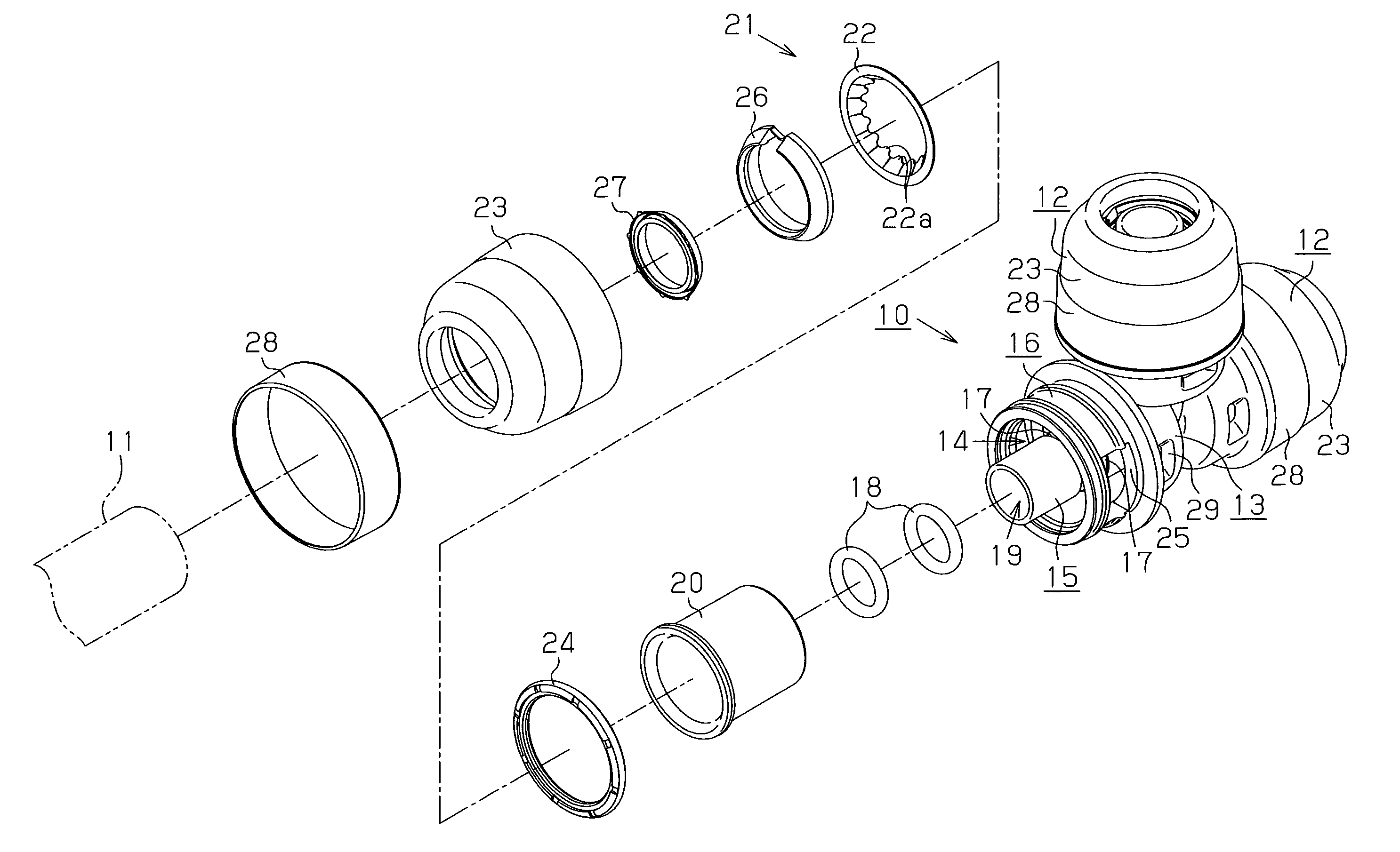
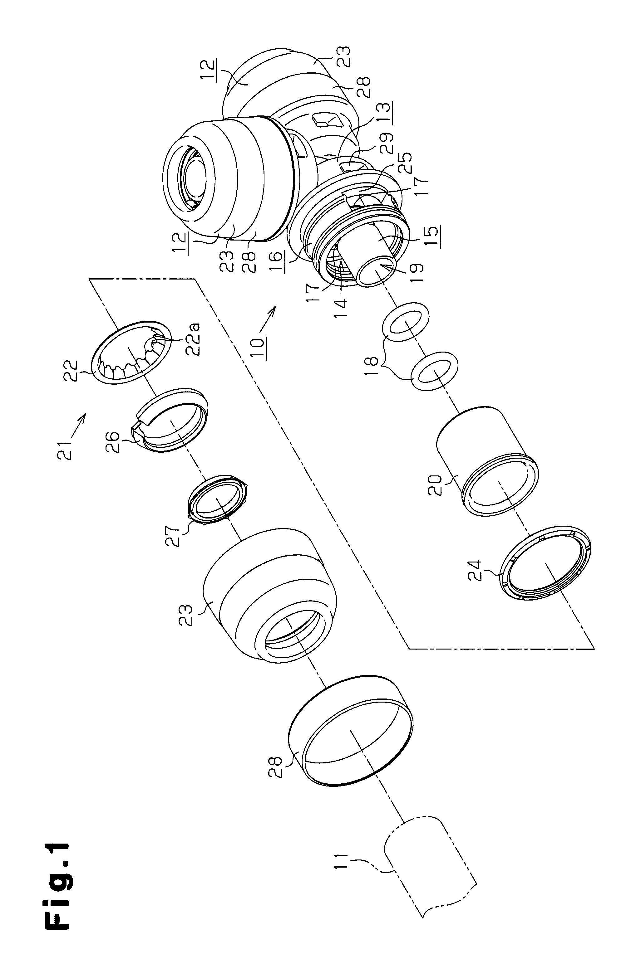
[0043]A joint according to a first embodiment of the present invention will now be described in detail with reference to FIGS. 1 to 10.

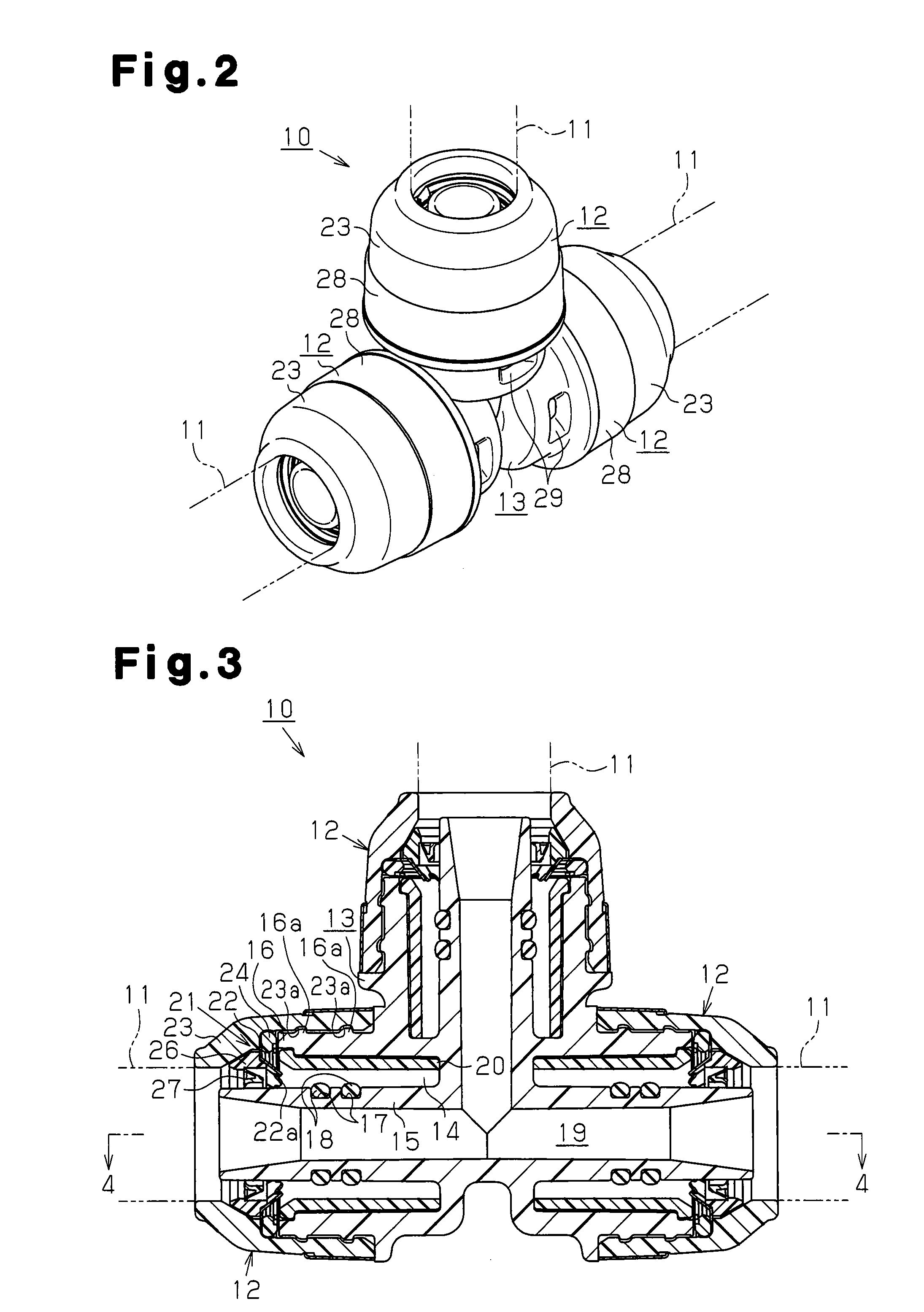
[0044]As illustrated in FIGS. 1 and 2, a joint 10 includes a joint body 13. The joint body 13 has three pipe joint portions 12 extending in three directions. Each of the pipe joint portions 12 has a cylindrical shape and a plastic pipe 11 is joined to the joint portion 12. The joint body 13 is formed of a rubber incorporating plastic such as polyphenylene sulfide (PPS) plastic incorporating rubber. The plastic pipes 11 are each formed of plastic such as polyolefin (for example, cross-linked polyethylene and polybutene). Since the pipe joint portions 12 are identical, the description herein will be focused on one of the joint portions 12.

[0045]With reference to FIGS. 1 and 3, an inner tubular portion 15 and an outer tubular portion 16, which form an insertion space 14 for receiving the corresponding plastic pipe 11, are formed integrally with the join...

second embodiment

[0077]A joint according to a second embodiment of the invention will now be described with reference to FIGS. 11 and 12. The description below is focused on the difference between the second embodiment and the first embodiment.

[0078]As illustrated in FIGS. 11 and 12, each view window 25 is configured by a cutout having a rectangular shape extending axially from the outer end of the outer tubular portion 16, as viewed from the front. The axial width D1 of the cutout is greater than the width D2 covering the range corresponding to the two fitting grooves 17. The radial length Y1 of the cutout is greater than the radial length Y2 of each fitting groove 17. As a result, the view windows 25 ensure visibility of the fitting grooves 17 each as a whole and the sealing members 18 each as a whole when the sealing members 18 are fitted in the fitting grooves 17.

[0079]To manufacture the joint 10 of the second embodiment, the insertion hole 47 formed in each split mold member 31a, 31b used in th...


PUM

PropertyMeasurementUnit
widthaaaaaaaaaa
lengthaaaaaaaaaa
body structureaaaaaaaaaa

Abstract

An inner tubular portion and an outer tubular portion 16 for forming an insertion space for a plastic pipe are formed integrally with a joint body. Two fitting grooves are formed in the outer peripheral surface of the inner tubular portion 15. Two sealing members for maintaining water-tightness in the gap between the plastic pipe received in the insertion space and the inner tubular portion are fitted in the corresponding fitting grooves 17. A pair of view windows for visually checking the fitting grooves and the sealing members, which are fitted in the fitting grooves, from the exterior are formed in the outer tubular portion. The view windows are arranged at opposing positions.

Description

CROSS REFERENCE TO RELATED APPLICATIONS[0001]This application is a divisional of U.S. application Ser. No. 13 / 504,052, filed on Apr. 25, 2012, which is a U.S. Nationalization of PCT Application Number PCT / JP2011 / 077426, filed on Nov. 28, 2011, which claims priority to Japanese Patent Application No. 2011-121606, filed on May 31, 2011 and International Application No. PCT / JP2011 / 069591, filed Aug. 30, 2011, the entireties of which are incorporated herein by reference.FIELD OF THE INVENTION[0002]The present invention relates to a joint used in a piping system such as a feed-water system or a hot water supply system and a method for manufacturing the joint. More specifically, the invention relates to a joint and a method for manufacturing a joint, in which an outer tubular portion and an inner tubular portion for forming a pipe insertion space are formed integrally with a joint body, and a fitting groove formed in the outer peripheral surface of the inner tubular portion and a sealing ...

Claims


Application Information

Patent Timeline
Patent Type & Authority Applications(United States)
IPC IPC(8): F16L55/00
CPCB29C45/44F16L37/091B29L2031/246F16L55/00B29C45/2628B29C45/006B29C45/261B29C45/14F16L37/12F16L41/08F16L47/08
Inventor HAYASHI, NOBUHIKONAKAMURA, KOICHIOKITA, MASAHIRO
Owner ONDA SEISAKUSHO KK
Why Eureka
Try Eureka