Transformer

a transformer and transformer technology, applied in transformers/inductance details, transformers/inductances magnetic cores, electrical apparatus, etc., can solve the problems of many technical bottlenecks, easy hi-pot and short circuit between, and disobey the goal of minimization, so as to prevent the generation of undesired air gaps, reduce the risk of deformation of the first and second magnetic permeable devices during the sintering procedure, and increase the magnetic flux path high magnetic permeability

Inactive Publication Date: 2014-10-02
DELTA ELECTRONICS INC
View PDF4 Cites 13 Cited by
  • Summary
  • Abstract
  • Description
  • Claims
  • Application Information

AI Technical Summary

Benefits of technology

[0024]As mentioned above, in the transformer of the invention, two ends of the second magnetic permeable device are configured with a first flange and a second flange, so that the risk of deformations of the first and second magnetic permeable devices during the sintering procedure can be sufficiently decreased. This can prevent the generation of the undesired air gap. In addition, since the proportion of the material with high magnetic permeability in the magnetic flux path increases, the magnetic permeability of the entire transformer can be further increased.
[0025]Moreover, there are three first protrusions and three second protrusions separately disposed at two ends of the first magnetic permeable device, and each of the first and second protrusions is configured with a corresponding electrode for electrically connecting to the primary or secondary winding wire. Accordingly, the withstanding voltage of the transformer can be enhanced without increasing the dimension of the first magnetic permeable device, thereby decreasing the risk of hi-pot between the primary and secondary winding wires. This can be achieved by the fact that the creeping withstanding voltage of each electrode is smaller than the withstanding voltage of air. Accordingly, when the creeping distance between the primary and secondary winding wires increases without enlarging the air distance, the withstanding voltage of the entire transformer can be improved as the dimension of the transformer is not increased. In more specific, since the protrusions can increase the creeping distance between the primary and secondary winding wires, the withstanding voltage of the entire transformer can be improved without increasing the dimension of the transformer.

Problems solved by technology

However, many technical bottlenecks are encountered during the minimization of the transformer.
For example, when the size of the transformer is smaller and smaller, the primary and secondary winding wires thereof are too close, so the hi-pot and short circuit therebetween may easily occur as the high voltage is applied.
In order to prevent this problem, it is needed to extend the length of the cores for winding the winding wire, which obviously disobeys the goal of minimization.

Method used


Image

  • Transformer
  • Transformer
  • Transformer

Examples


Embodiment Construction

[0035]The present invention will be apparent from the following detailed description, which proceeds with reference to the accompanying drawings, wherein the same references relate to the same elements. To be noted, the drawings are for illustrations only and are not to limit the dimensions and scales of the real objects. The real dimensions and scales thereof may have different designs according to the actual requirement.

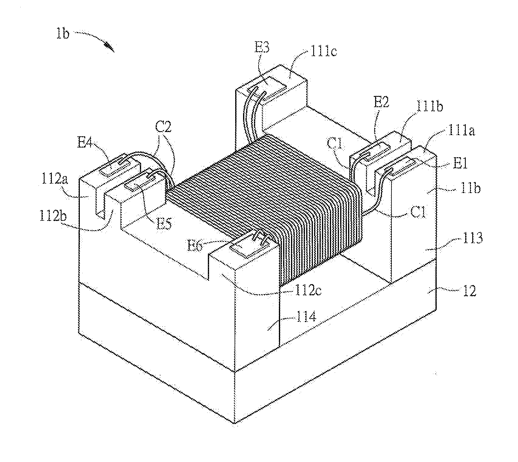
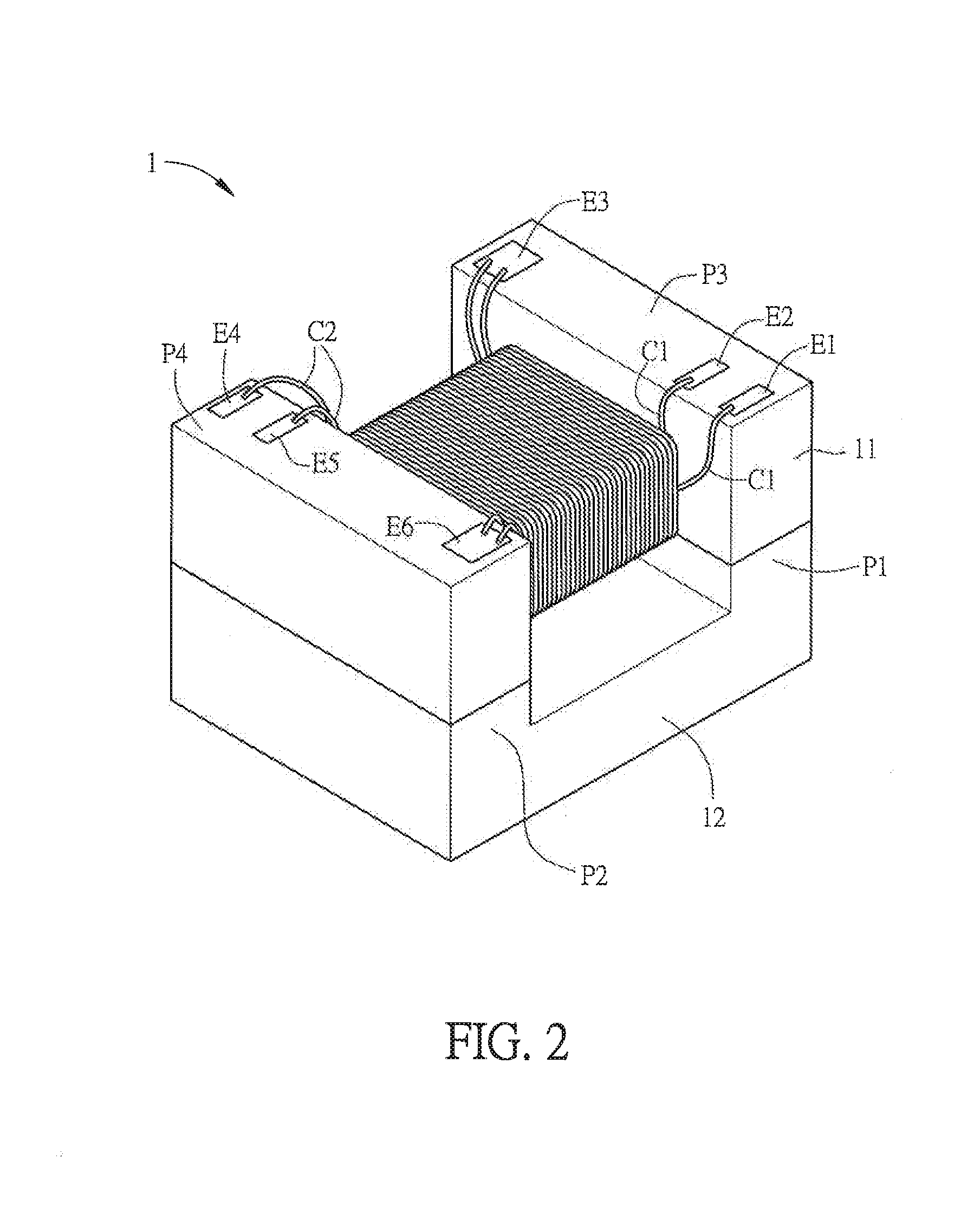
[0036]FIG. 2 is schematic diagram showing a transformer 1 according to an embodiment of the invention, FIG. 3A is a side view of a first magnetic permeable device 11 and a second magnetic permeable device 12, and FIG. 3B is a top view of the first magnetic permeable device 11. Referring to FIG. 2 in view of FIGS. 3A and 3B, the transformer 1 includes a first magnetic permeable device 11, a primary winding wire C1, a secondary winding wire C2 and a second magnetic permeable device 12.

[0037]The first magnetic permeable device 11 is, for example, silicon steel sheet, ...


PUM

PropertyMeasurementUnit
magnetic permeabilityaaaaaaaaaa
distanceaaaaaaaaaa
magnetic fluxaaaaaaaaaa

Abstract

A transformer includes a first magnetic permeable device, a primary winding wire, a secondary winding wire and a second magnetic permeable device. The primary winding wire and the secondary winding wire are wound on the first magnetic permeable device. The second magnetic permeable device includes a first flange and a second flange. The first flange is disposed at one end of the second magnetic permeable device, and the second flange is disposed at the other end of the second magnetic permeable device. The first flange and the second flange are connected to the first magnetic permeable device. The magnetic permeability of the second magnetic permeable device is larger than that of the first magnetic permeable device.

Description

CROSS REFERENCE TO RELATED APPLICATIONS[0001]This Non-provisional application claims priority under 35 U.S.C. §119(a) on Patent Application No(s). 102111782 and 102111783 filed in Taiwan, Republic of China on Apr. 1, 2013, the entire contents of which are hereby incorporated by reference.BACKGROUND OF THE INVENTION[0002]1. Field of Invention[0003]The present invention relates to a transformer.[0004]2. Related Art[0005]The transformer is an electronic device used for boosting or descending voltage according to the Faraday's Law of induction, and it is mainly applied to increase and decrease the voltage of AC power, to change the impedance or to isolate circuits.[0006]FIG. 1 is a schematic diagram showing a first magnetic permeable device a and a second magnetic permeable device b of a conventional transformer, which are to be wound by winding wires. Referring to FIG. 1, an air gap c is naturally formed in the sintering process due to the structures and shapes of the first magnetic pe...

Claims


Application Information

Patent Timeline
Patent Type & Authority Applications(United States)
IPC IPC(8): H01F27/24H01F27/29
CPCH01F27/29H01F27/24H01F3/10H01F27/2828H01F2003/106
Inventor TAI, CHIN-CHUNG
Owner DELTA ELECTRONICS INC
Why Eureka
Try Eureka