
Projection-type image display device, image projection control device, and image projection control method

a technology of image display device and control device, which is applied in the direction of instruments, computing, electric digital data processing, etc., can solve the problems of lowering the stability of the arc discharge in the light source and the image display quality, so as to improve the life of the light source lamp, maintain color balance, and improve image quality

Active Publication Date: 2014-10-02
PANASONIC INTELLECTUAL PROPERTY MANAGEMENT CO LTD
View PDF2 Cites 2 Cited by
  • Summary
  • Abstract
  • Description
  • Claims
  • Application Information

AI Technical Summary

Benefits of technology

The patent is about a new type of image display device that controls the timing and application of current pulses to increase the lifetime of the light source and improve image quality. Previous devices had a problem where the current value decreased during a specific color's period, leading to polarity inversion and lowered stability of the arc discharge in the light source. The new technology solves this problem by controlling the current pulse application to achieve the same number of applications for each color and reaching the required current value for each color. This results in higher stability of arc discharge and improved image display quality.

Problems solved by technology

As a result, polarity inversion occurs with a low current value, thus lowering the stability of the arc discharge in the light source and lowering the image display quality.

Method used


Image

  • Projection-type image display device, image projection control device, and image projection control method
  • Projection-type image display device, image projection control device, and image projection control method
  • Projection-type image display device, image projection control device, and image projection control method

Examples


embodiment 1

[0024]Embodiment 1 will be described below with reference to FIGS. 1 to 8.

1-1. Overview

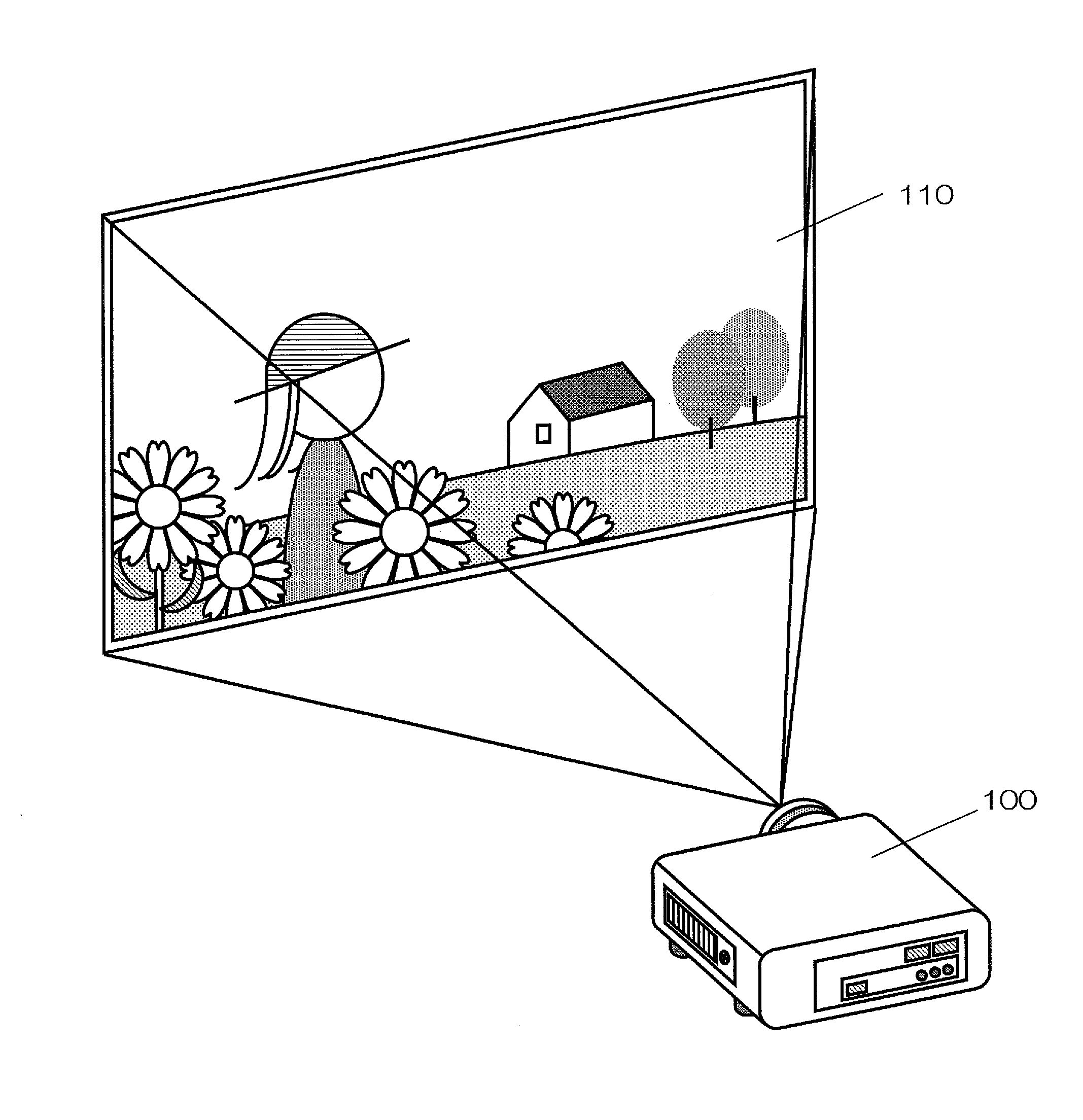
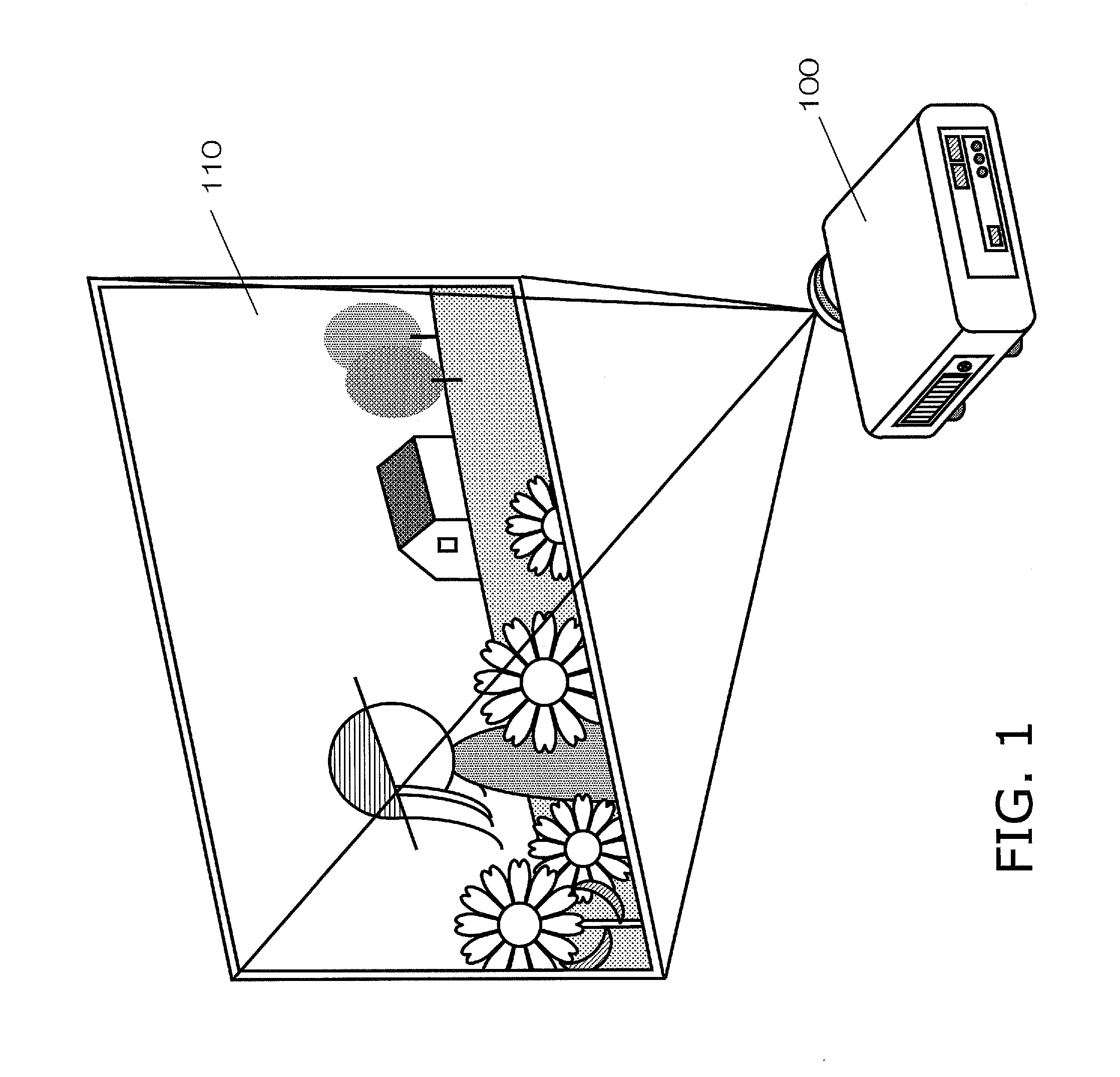
[0025]FIG. 1 shows a usage state of a projector 100 (example of a projection-type image display device) according to Embodiment 1. The projector 100 generates an image by using a DMD to reflect light emitted by a light source unit, and projects the generated image onto a screen 110 via a projection optical system.

1-2. Configuration

[0026]1-2-1. Overall Configuration

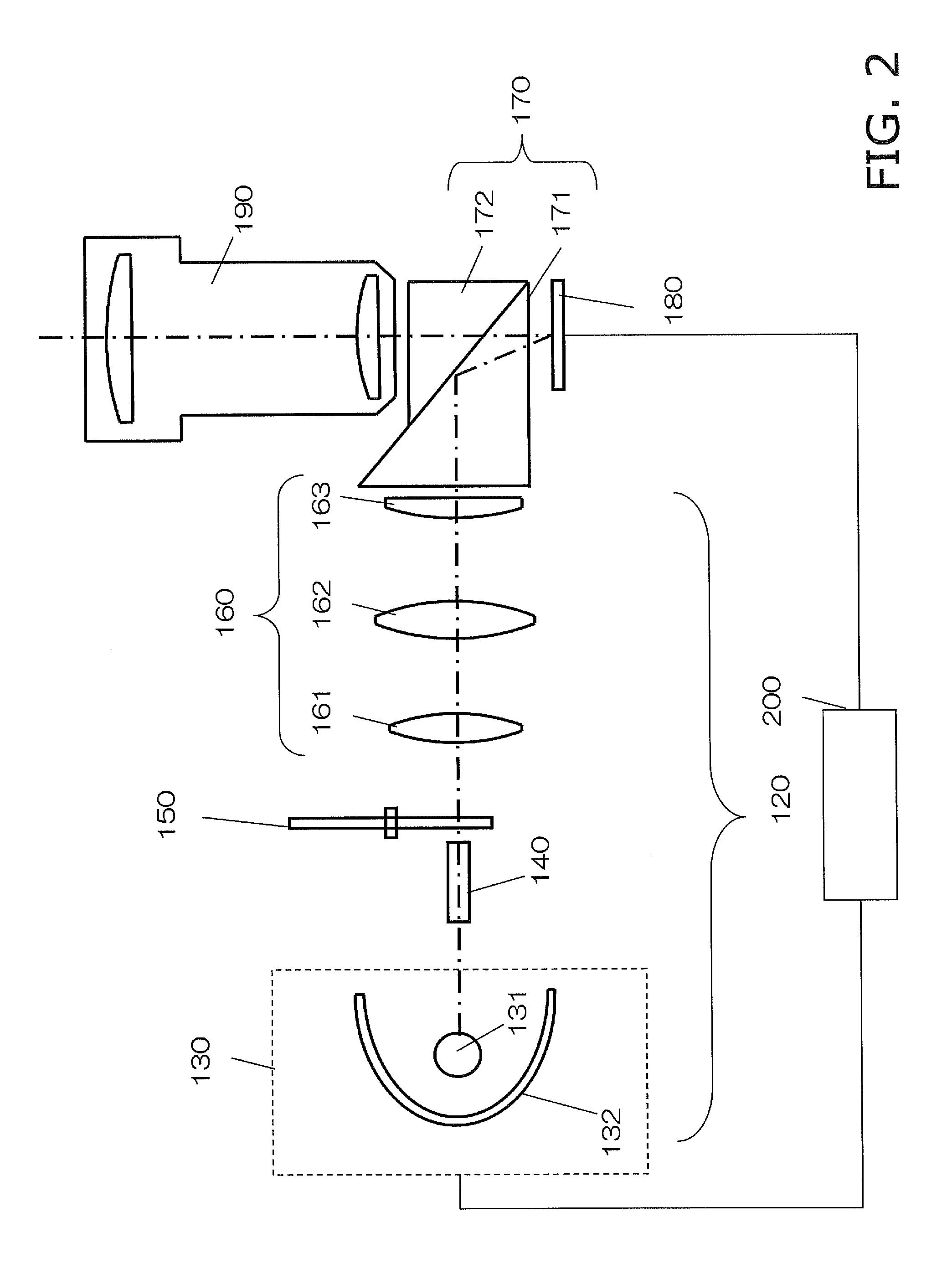
[0027]The overall configuration of the projector 100 will be described below with reference to FIGS. 1 and 2. FIG. 2 is a diagram schematically showing the overall configuration of the projector 100 according to Embodiment 1.

[0028]The following describes the detailed configuration of the projector 100.

[0029]The projector 100 includes a light source unit 130 (example of a light source unit), a rod integrator 140, a color wheel 150 (example of a color generation unit), a relay optical system 160, a total reflection prism 170, a digital mir...

modified example 1

1-5. Modified Example 1

[0064]Embodiment 1 describes the case where the polarity inversion timing is controlled in synchronization with the rotation cycle of the color wheel 150 as shown in FIG. 5. Modified Example 1 describes an example in which multiple polarity inversion cycles are set.

[0065]Originally, light quantity changes occur due to temporary changes in the current value when the polarity of the light source unit 130 is inverted. For this reason, there are cases where the color balance of the image changes, although to a slight degree, when the polarity inversion cycle is switched. Accordingly, in Modified Example 1, the perceptibility of color balance changes is reduced by making a scene change determination and changing one polarity inversion cycle to another polarity inversion cycle based on the determination result.

[0066]The following describes the content of control performed by the control unit 200 of Modified Example 1 with reference to FIG. 8.

[0067]FIG. 8 is a diagra...

embodiment 2

[0074]Embodiment 2 describes a projector that employs a method of suppressing flickering caused by steep power changes, in addition to the control of Embodiment 1.

2-1. Configuration

[0075]The projector of the present embodiment has the same configuration as the projector 100 of Embodiment 1 shown in FIGS. 1 to 3, and therefore a description of the configuration will not be given. Also, the same figures and reference signs will be used below when referring to configurations and functions that are the same as in Embodiment 1.

2-2. Operations

[0076]The control unit 200 (FIG. 3) of the projector 100 of the present embodiment references the input signal saturations calculated for frames, each of which is made up of multiple sub frames, and based on the correlation with the previous and subsequent frames, changes the light quantities in sub frames so as to reduce the light quantity difference with respect to the previous and subsequent frames. Here, control is performed such that the necessa...


PUM


Abstract

The projection-type image display device includes a light source unit, a color generation unit provided on the optical path of emitted light from the light source unit and configured to generate multiple colors of light from emitted light from the light source in a time-division manner by rotating at a predetermined rotation cycle, a light modulation unit, and a control unit. In accordance with a color component of the input image signal, the control unit sets current values for current to be applied to the light source unit and a polarity inversion timing for inverting the polarity of the light source unit. The control unit applies current having the current values to the light source unit while inverting the polarity according to the polarity inversion timing. The control unit shifts the polarity inversion timing according to change in the current values for current to be applied to the light source unit.

Description

PRIORITY[0001]This application claims priority to Japanese Patent Application No. 2013-075616 filed on Apr. 1, 2013 and Japanese Patent Application No. 2014-059860 filed on Mar. 24, 2014. The entire disclosure of Japanese Patent Application 2013-075616 and Japanese Patent Application No. 2014-059860 is hereby incorporated herein by reference.BACKGROUND[0002]1. Technical Field[0003]The present disclosure relates to a projection-type image display device, an image projection control device, and an image projection control method for performing time-division color display.[0004]2. Background Art[0005]Patent Document 1 (JP 2003-518643A) discloses a projection-type image display device. This projection-type image display device includes a color wheel that has multiple segments, and a projection optical system that has a light source (lamp light source). With this projection-type image display device, constant power is supplied to the light source while changing the polarity of a square w...

Claims


Application Information

Patent Timeline
Patent Type & Authority Applications(United States)
IPC IPC(8): G09G5/10
CPCG09G5/10G09G3/3406G09G3/002G09G2310/0235G09G2320/043
Inventor HARAGUCHI, MASAHIROINOUE, MASUTAKA
Owner PANASONIC INTELLECTUAL PROPERTY MANAGEMENT CO LTD
Learn More