
Detection circuit

Active Publication Date: 2014-10-02
ACER INC
View PDF5 Cites 9 Cited by
  • Summary
  • Abstract
  • Description
  • Claims
  • Application Information

AI Technical Summary

Benefits of technology

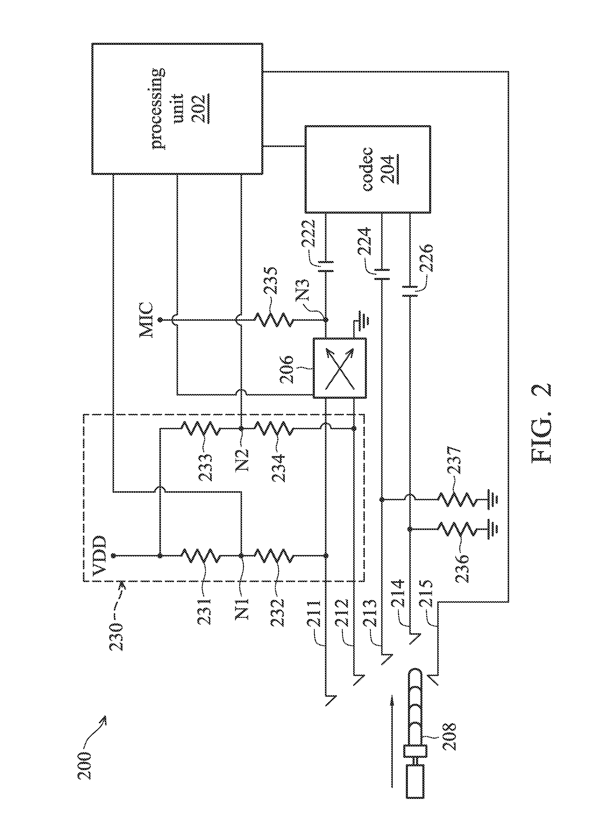
The patent is about a detection circuit that can identify different parts of an earphone plug. It includes a voltage detection circuit, a processing unit, a microphone switch, and a codec. The circuit detects the signal transduction area(s) connected by the first and second pins of the plug and generates a switch-control signal. This signal controls the microphone switch, which connects the two pins to the microphone output node and ground when the processing unit determines that the pins are connected to a microphone area or a ground area of the plug. The codec is also connected to the microphone output node. The technical effect of this invention is that it allows for accurate detection of the various parts of an earphone plug and ensures that the microphone switch is always connected to the correct pins.

Problems solved by technology

However, the plugs of the earphone combined with the microphone come in two types, and today's electronic devices typically can only determine the differences between the earphone combined with microphone and the normal earphone.
When the user uses the plug, which is another type of earphone combined with a microphone, the electronic device loses the ability to determine its nature.

Method used


Image

  • Detection circuit
  • Detection circuit
  • Detection circuit

Examples


Embodiment Construction

[0017]The following description is of the best-contemplated mode of carrying out the invention. This description is made for the purpose of illustrating the general principles of the invention and should not be taken in a limiting sense. The scope of the invention is best determined by reference to the appended claims.

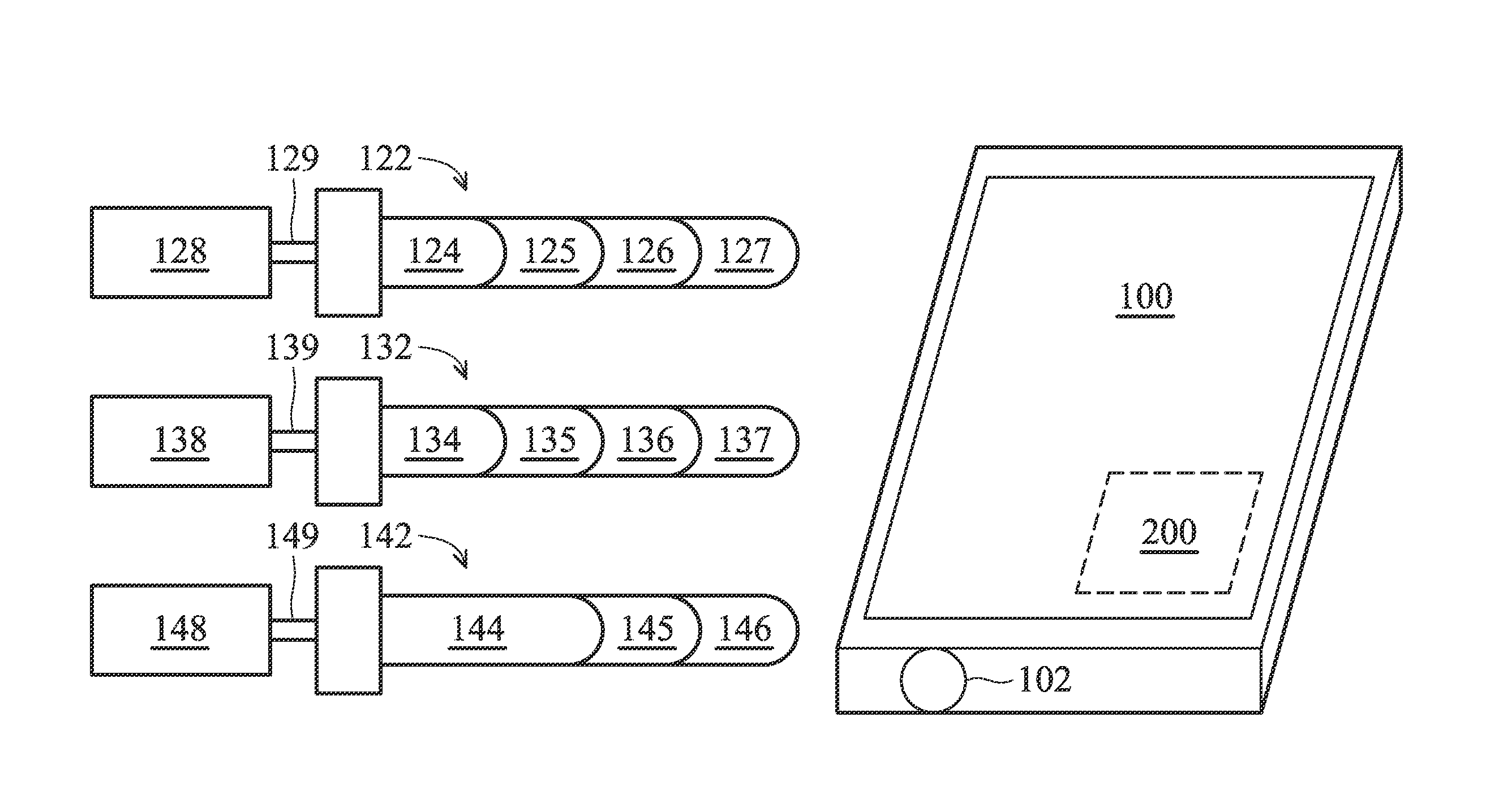
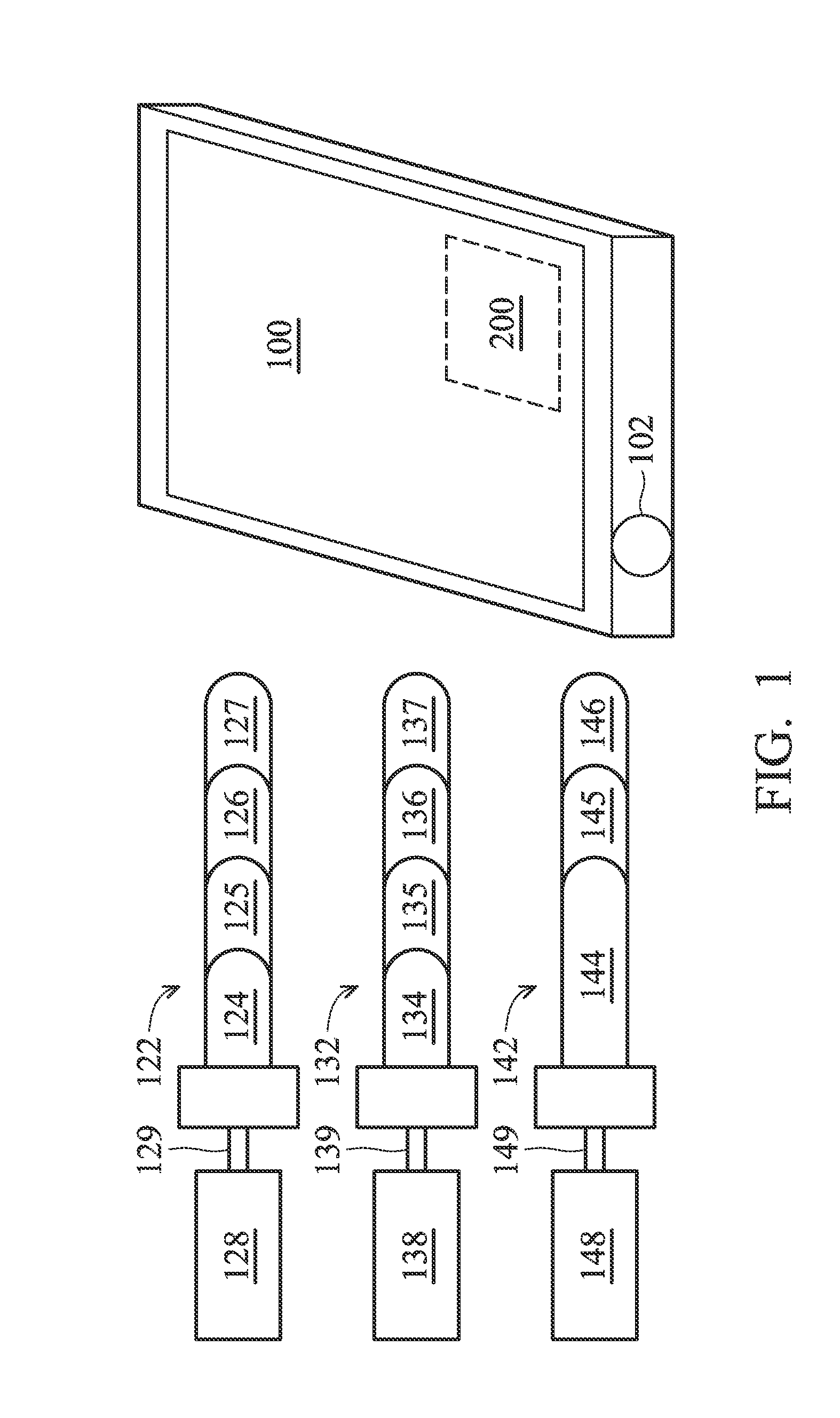
[0018]The electronic device as shown in FIG. 1 can accommodate three different types of plugs. In FIG. 1, the electronic device 100 comprises the socket 102 and the detection circuit 200. At any one time, the socket 102 can accommodate one of the following: the plug 122 of a microphone earphone 128 of the first type, the plug 132 of a microphone earphone 138 of the second type, or the plug 142 of a normal earphone 148. The microphone earphone 128 of the first type is connected to the plug 122 through a cable 129, and the microphone earphone 128 of the first type includes the earphone having the left and right stereo channels and the microphone. The plug 122 comprises f...


PUM


Abstract

A detection circuit is disclosed, in which the first and second pins are arranged to connect to at least one signal transduction area of the plug, such that a voltage division circuit generates first and second division voltages accordingly. A processing unit determines the signal transduction area(s) connected by the first and second pins by the first and second division voltages. When detecting that the first and second pins separately connect the microphone area and the ground area of the plug, the processing unit controls a microphone switch to connect the first pin to the microphone output node and the second pin to the ground. When detecting that the first pin and the second pin separately connect the ground area and the microphone area, the processing unit controls the microphone switch to connect the first pin to the ground and the second pin to the microphone output node.

Description

CROSS REFERENCE TO RELATED APPLICATIONS[0001]This Application claims priority of Taiwan Patent Application No. 102111643, filed on Apr. 1, 2013, the entirety of which is incorporated by reference herein.BACKGROUND OF THE INVENTION[0002]1. Field of the Invention[0003]The present invention relates to an electronic device, and in particular to an electronic device capable of automatically detecting the type of plug.[0004]2. Description of the Related Art[0005]Today's electronic devices, especially handheld electronic devices, are often equipped with an earphone socket to allow the user to use earphones to listen to music, record sound, or communicate with others, among other uses. Since a style of earphone that is combined with a microphone is becoming a trend, the electronic device needs to determine whether the earphone is a normal earphone, or one that is combined with a microphone, by the accommodated earphone plug. However, the plugs of the earphone combined with the microphone co...

Claims


Application Information

Patent Timeline
IPC IPC(8): H04R29/00
CPCH04R29/00H04R29/001H04R29/004H04R2201/107H04R2420/05H01R24/58
Inventor TU, PO-JENCHANG, TZU-CHUNCHANG, JIA-RENYU, MING-CHUNTAI, KUEI-TING
Owner ACER INC
Learn More