

Vehicle comprising a mounted-implement coupling and mounted implement therefor
a technology of implement coupling and implement, which is applied in the field of agricultural vehicles, can solve the problems of uncontrolled leakage of hydraulic fluid in the vehicle, the speed and ease of implementation of the coupling procedure,
- Summary
- Abstract
- Description
- Claims
- Application Information
AI Technical Summary
Benefits of technology
Problems solved by technology
Method used
Image

Examples
Embodiment Construction
[0022]The following is a detailed description of example embodiments of the invention depicted in the accompanying drawings. The example embodiments are presented in such detail as to clearly communicate the invention and are designed to make such embodiments obvious to a person of ordinary skill in the art. However, the amount of detail offered is not intended to limit the anticipated variations of embodiments; on the contrary, the intention is to cover all modifications, equivalents, and alternatives falling within the spirit and scope of the present invention, as defined by the appended claims.
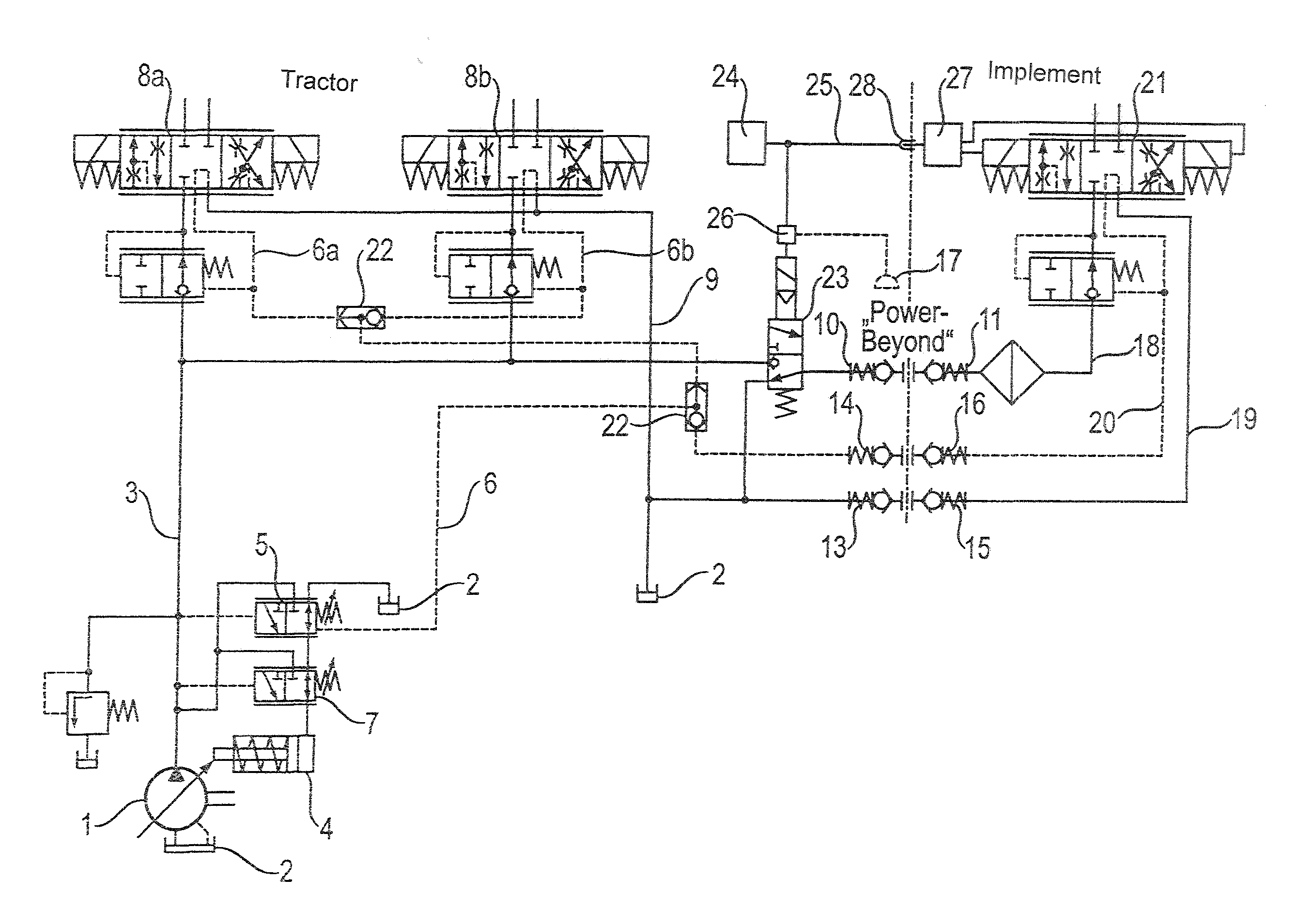
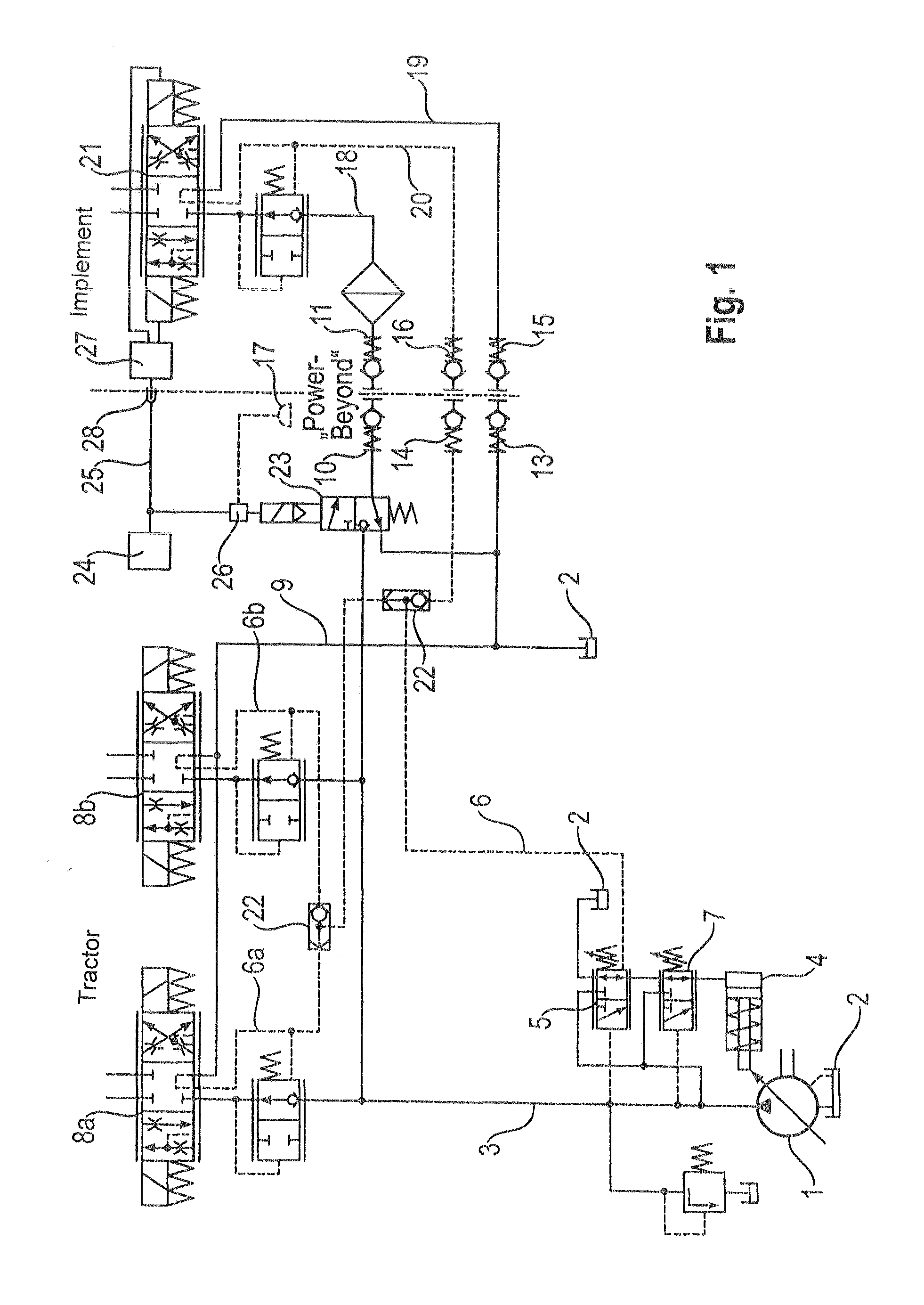
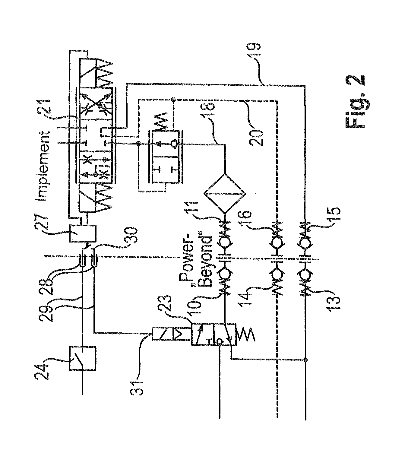
[0023]The hydraulic system on the tractor side is a development of the Power-Beyond™ system, which is known per se. The hydraulic system comprises a variable-displacement pump 1, which is fixedly coupled to a diesel engine (not depicted), and which rotates when the diesel engine is operating. A suction connection of the variable-displacement pump 1 is connected to a tank 2 for hydraulic flu...
PUM
 Abstract
Description
Claims
Application Information