Fuel cell monitoring device

a fuel cell and monitoring device technology, applied in the direction of resistance/reactance/impedence, electrochemical generators, instruments, etc., can solve the problems of insufficient detection accuracy of conventional techniques for detecting a water content inside the fuel cell, significant influence on the calculation gas reaction resistance, and difficulty in detecting a correct excess amount of water inside the fuel cell with a high accuracy. , to achieve the effect of high accuracy, high efficiency and high accuracy

Active Publication Date: 2014-10-02
DENSO CORP +2
View PDF6 Cites 24 Cited by
  • Summary
  • Abstract
  • Description
  • Claims
  • Application Information

AI Technical Summary

Benefits of technology

[0015]That is, the fuel cell monitoring device according to the exemplary embodiment can calculate the first diffusion resistance by subtracting the second diffusion resistance, which shows the diffusion characteristics varying depending on the dried-up of the inside of the fuel cell from the reaction gas diffusion characteristics. The fuel cell monitoring device obtains the first diffusion resistance as a quantitative value regarding the diffusion characteristics of the reaction gas varying due to the flooding in the inside if the fuel cell. As a result, it is possible to detect the excess state of the water content in the inside of the fuel cell with high accuracy.
[0016]Still further, the fuel cell monitoring device according to the exemplary embodiment further has a water content calculation section which calculates the water content in the inside of the fuel cell on the bas...

Problems solved by technology

In addition, the calculated gas reaction resistance is significantly affected by a change of a gas concentration generated when a gas supply amount is changed.
Accordingly, the conventional technique for detecting a water content in the inside of the fuel cell has an insufficient detection accuracy because of calculating the water content of the fuel cell on the basis of the gas reaction resistance only.
In other words, it is difficult for the conventional techniques to detect a correct excess amount of water in the inside of the fuel cell with a high accuracy.
It is possible to detect a correct excess amount of water contained in the inside of the fuel cell on the ba...

Method used


Image

  • Fuel cell monitoring device
  • Fuel cell monitoring device
  • Fuel cell monitoring device

Examples


Embodiment Construction

[0037]Hereinafter, various embodiments of the present invention will be described with reference to the accompanying drawings. In the following description of the various embodiments, like reference characters or numerals designate like or equivalent component parts throughout the several diagrams.

Exemplary Embodiment

[0038]A description will be given of a fuel cell monitoring device according to an exemplary embodiment with reference to FIG. 1 to FIG. 18.

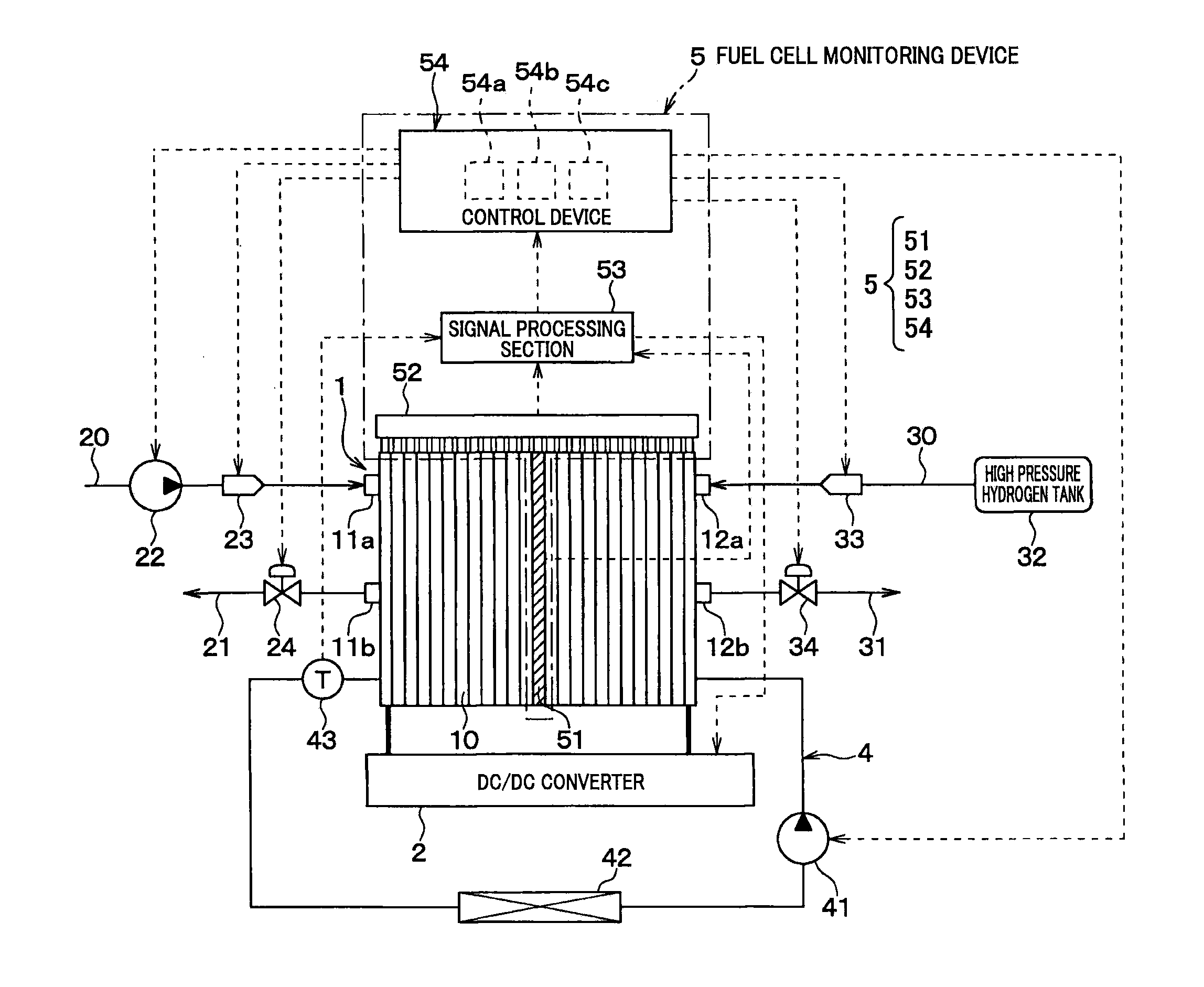
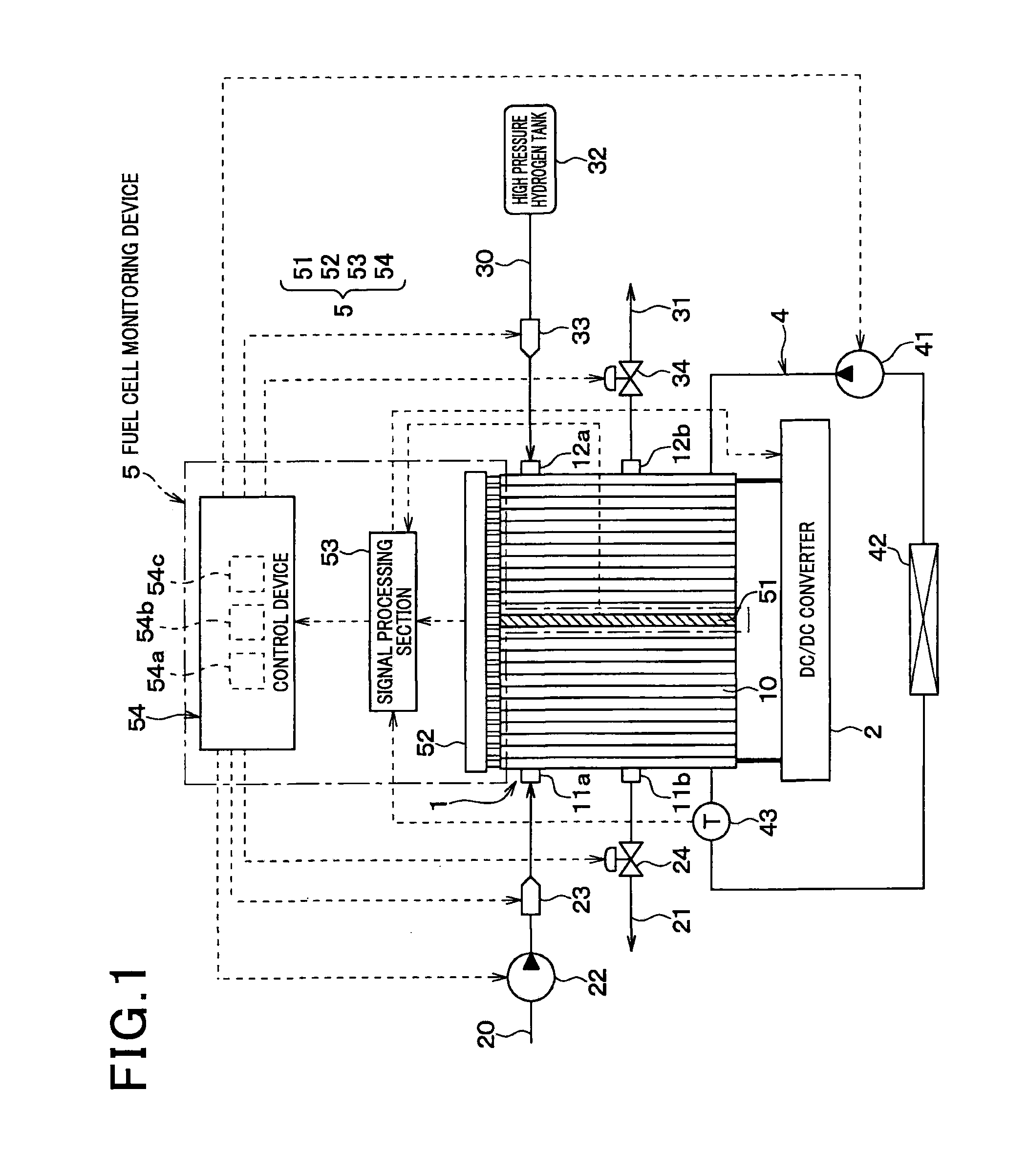
[0039]FIG. 1 is a view showing an overall structure of a fuel cell system comprised of a fuel cell 1 and the fuel cell monitoring device 5 according to the exemplary embodiment. The fuel cell monitoring device 5 according to the exemplary embodiment is used in a fuel cell system of a fuel cell vehicle as one type of electric vehicles. The fuel cell monitoring device 5 according to the exemplary embodiment monitors the condition of the fuel cell 1 mounted to the fuel cell vehicle.

[0040]The fuel cell 1 performs an electrochemical reac...


PUM


Abstract

In a fuel cell monitoring device, a gas-diffusion resistance calculation section calculates a gas-diffusion resistance Rtotal indicating a difficulty of diffusing reaction gas to a catalyst layer in a fuel cell based on a gas reaction resistance Rct calculated by a resistance calculation section. A second diffusion resistance calculation section calculates a second diffusion resistance Rdry varying depending on a dried-up in the fuel cell based on a proton transfer resistance Rmem calculated by the resistance calculation section. A first diffusion resistance calculation section calculates a first diffusion resistance Rwet varying depending on a flooding in the fuel cell by subtracting the second diffusion resistance Rdry from the gas-diffusion resistance Rtotal. A water content calculation section calculates a water content of the fuel cell based on the first diffusion resistance. A recovery control section adjusts the water content in the fuel cell based on the calculated water content.

Description

CROSS-REFERENCE TO RELATED APPLICATION[0001]This application is related to and claims priority from Japanese Patent Application No. 2013-76733 filed on Apr. 2, 2013, the contents of which are hereby incorporated by reference.BACKGROUND OF THE INVENTION[0002]1. Field of the Invention[0003]The present invention relates to fuel cell monitoring devices for monitoring various operational conditions of a fuel cell comprised of one or more unit cells.[0004]2. Description of the Related Art[0005]There have been known a conventional technique to detect a water content in a fuel cell on the basis of impedances of the fuel cell at different frequencies, and adjust the water content in the fuel cell to an optimum value. For example, Japanese patent laid open publication No. JP 2003-86220 discloses such a conventional technique.[0006]The technique disclosed in JP 2003-86220 calculates a resistance component R1 and a resistance component R2, and estimates a water content of the fuel cell on the b...

Claims


Application Information

Patent Timeline
IPC IPC(8): H01M8/04
CPCH01M8/04119H01M8/04582H01M8/04552H01M8/04492H01M8/04388H01M8/04395H01M8/04641H01M8/04402H01M8/0441H01M8/04701H01M2008/1095Y02E60/50
Inventor ISHIKAWA, YUJIKATO, IKUYASUYAMADA, TAKASHISAKAJOH, YUUICHISUEMATSU, KEIGO
Owner DENSO CORP
Why Eureka
Try Eureka