Spark plug for internal combustion engines and mounting structure for the spark plug

a technology for spark plugs and internal combustion engines, which is applied to spark plugs, machines/engines, and anti-theft devices, etc., can solve the problems of high flow speed of air-fuel mixture in combustion chambers, shortened life of spark plugs, and disproportionate wear of parts, so as to achieve easy ignition, enhance ignitability of spark plugs, and retain the effect of resistance to carbon fouling

Active Publication Date: 2014-10-09
DENSO CORP
View PDF16 Cites 2 Cited by
  • Summary
  • Abstract
  • Description
  • Claims
  • Application Information

AI Technical Summary

Benefits of technology

[0015]As viewed in the axial direction of the plug, the spark plug is arranged such that the first sub ground electrode and the second sub ground electrode are located face to face sandwiching the opposing portion of the main ground electrode. Thus, the spark plug can be mounted to the internal combustion engine such that the main ground electrode is ensured not to be located upstream or downstream in the flow of the air-fuel mixture, with the first sub ground electrode being located upstream in the flow and the second sub ground electrode being located downstream in the flow.
[0016]The length of projection Hs1 of the first sub ground electrode from the tip of the housing satisfies Hs1<Hc+Gm. Thus, in the above arrangement condition, the flow directed to the main gap is prevented from being blocked by the first sub ground electrode located upstream, thereby allowing the flow to enter the main gap. As a result, the air-fuel mixture comes to be easily ignited in the main gap. At the same time, ignitability of the spark plug is enhanced, owing to the ease of flame growth.
[0017]Further, when carbon fouling occurs in the spark plug, i.e. when carbon fouling occurs in the porcelain tip portion of the spark plug, creating an electrically conductive state, and discharge can no longer be appropriately obtained in relation to the main ground electrode, discharge can be caused in the first sub gap. A discharge spark in this instance will burn off and eliminate the carbon. Thus, the portion from which the carbon has been eliminated is restored from the electrically conductive state to an insulated state, thereby retaining insulation properties of the porcelain tip portion. Therefore, appropriate discharge is caused between the center electrode and the main ground electrode and thus a discharge spark is obtained. In this way, resistance to carbon fouling is retained and the life of the spark plug is enhanced.
[0018]Further, the spark plug satisfies Gm<Gs1+Gg and Gm<Gs2+Gg. Thus, in the spark plug prior to the occurrence of carbon fouling, a discharge spark is prevented from being generated between the center electrode and the first sub ground electrode or between the center electrode and the second sub ground electrode. Thus, a discharge spark is obtained normally in the main gap. As a result, the air-fuel mixture is easily ignited in the main gap and thus flame is easily grown. Thus, ignitability of the spark plug is enhanced.
[0019]Further, spark plug satisfies Hs2≧Hs1 and Hc<Hs2, where Hs1 is the length of projection of the first sub ground electrode from the tip of the housing, Hs2 is the length of projection of the second sub ground electrode from the tip of the housing, and Hc is the length of projection of the center electrode from the housing. Thus, when a discharge spark generated in the main gap is expanded to a large extent by the gas flow in the above arrangement condition, the discharge spark is received by the second sub ground electrode. In other words, since the discharge spark is prevented from being expanded to a large extent and from being cut off, the discharge spark is sustained between the center electrode and the second sub ground electrode. Therefore, repetition of discharge cutoff and re-discharge is suppressed. As a result, the center electrode and the main ground electrode are suppressed from being worn out to thereby enhance the life of the spark plug. In addition, since the discharge spark is sustained as mentioned above, an ignition opportunity (i.e., an opportunity for the ignition which leads to the ignition) is well ensured and thus ignitability of the spark plug is enhanced.
[0020]As described above, according to the foregoing aspects, a spark plug for an internal combustion engine and a mounting structure for the spark plug are provided, with which ignitability and life of the spark plug are enhanced, while resistance to carbon fouling is retained.

Problems solved by technology

However, in the lean burn mentioned above, the flow speed of the air-fuel mixture is high in the combustion chamber.
Thus, these portions are likely to be disproportionately worn out (hereinafter this is referred to as disproportionate wear).
As a result, the life of the spark plug 9 is problematically shortened.
Thus, ignitability may be impaired.

Method used


Image

  • Spark plug for internal combustion engines and mounting structure for the spark plug
  • Spark plug for internal combustion engines and mounting structure for the spark plug
  • Spark plug for internal combustion engines and mounting structure for the spark plug

Examples


first embodiment

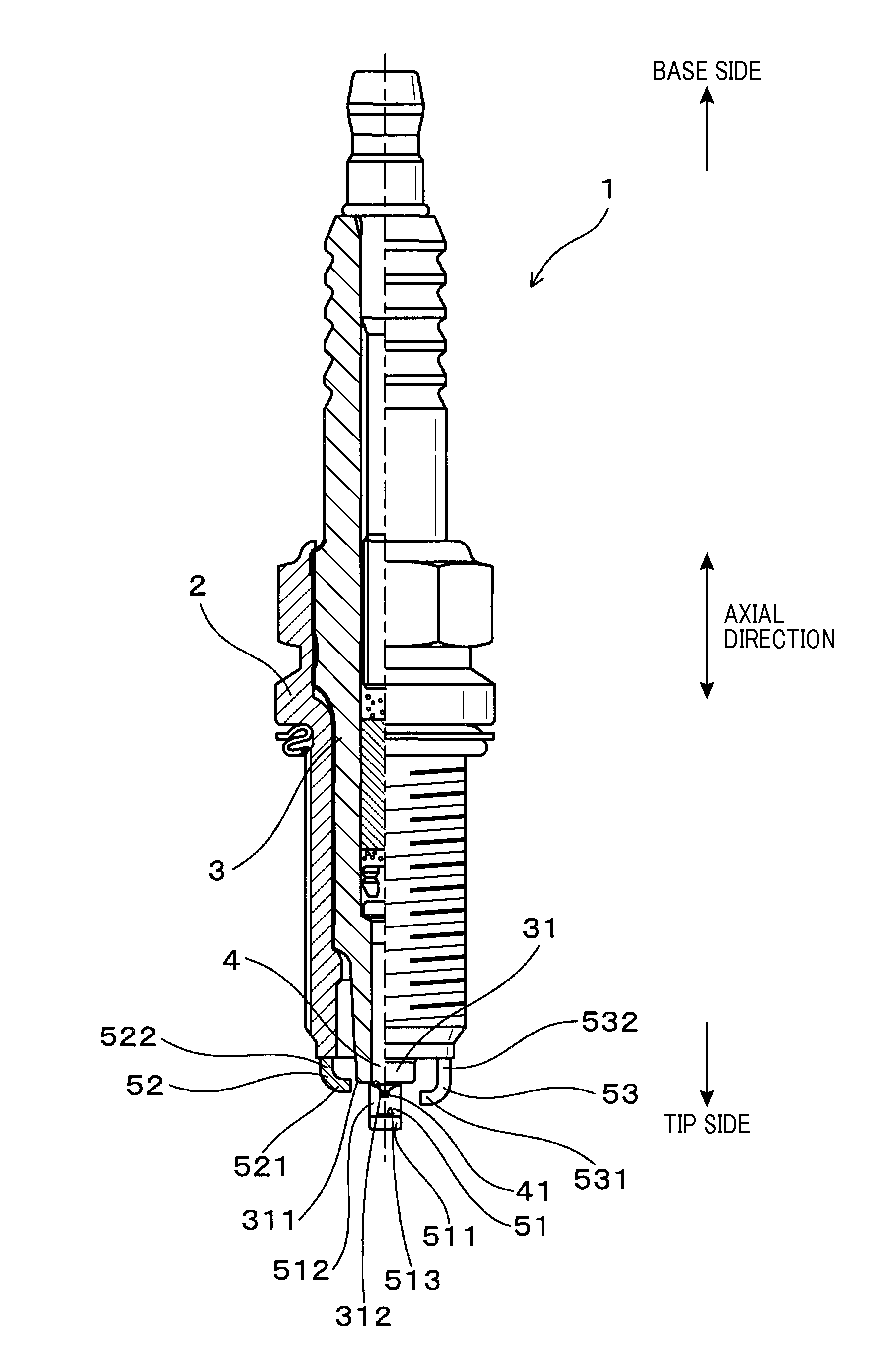
[0039]Referring to FIGS. 5 to 10, a spark plug of an embodiment is described.

[0040]As shown in FIG. 5, a spark plug 1 of the present embodiment includes: a cylindrical housing 2; a cylindrical insulation porcelain 3 held inside the housing 2 such that a porcelain tip portion 31 is projected from the housing 2; a center electrode 4 held inside the insulation porcelain 3, with a tip portion thereof being projected; and a main ground electrode 51, a first sub ground electrode 52 and a second sub ground electrode 53, which are connected to the housing 2.

[0041]As shown in FIG. 6, the main ground electrode 51 has an opposing portion 511 that faces the center electrode 4 in the axial direction of the plug (longitudinal direction of the spark plug 1: see FIG. 5) to form a main gap 61 in relation to the center electrode 4.

[0042]The first sub ground electrode 52 forms a first sub gap 62 in relation to an outer peripheral edge portion 311 in the porcelain tip portion 31.

[0043]The second sub gr...

experimental example 1

[0077]As shown in FIG. 11, in the present example, ignitability of a spark plug is researched by comparing A / F (Air-Fuel) limit values.

[0078]As a target of evaluation, the spark plug 1 shown in the first embodiment was dimensioned such that the base material (portion held inside the insulation porcelain 3) of the center electrode 4 had a maximum diameter of 2.3 mm, the electrode tip portion of the center electrode 4 had a diameter of 0.7 mm, the cross section of the opposing portion 511 of the main ground electrode 51 in the axial direction of the plug was substantially in a rectangular shape of 1.4 mm×2.6 mm, and the cross section of each of the opposing portions 521 and 531 of the first sub ground electrode 52 and the second sub ground electrode 53, respectively, in the axial direction of the plug was substantially in a rectangular shape of 1.2 mm×2.2 mm. Further, Hc was set to 4.0 mm, Gm was set to 0.8 mm, Gs1 and Gs2 were set to 0.5 mm, and Gg was set to 1.0 mm. Then, the spark ...

experimental example 2

[0086]As shown in FIG. 12, in the present example, durability of a spark plug was researched by comparing the numbers of re-discharges.

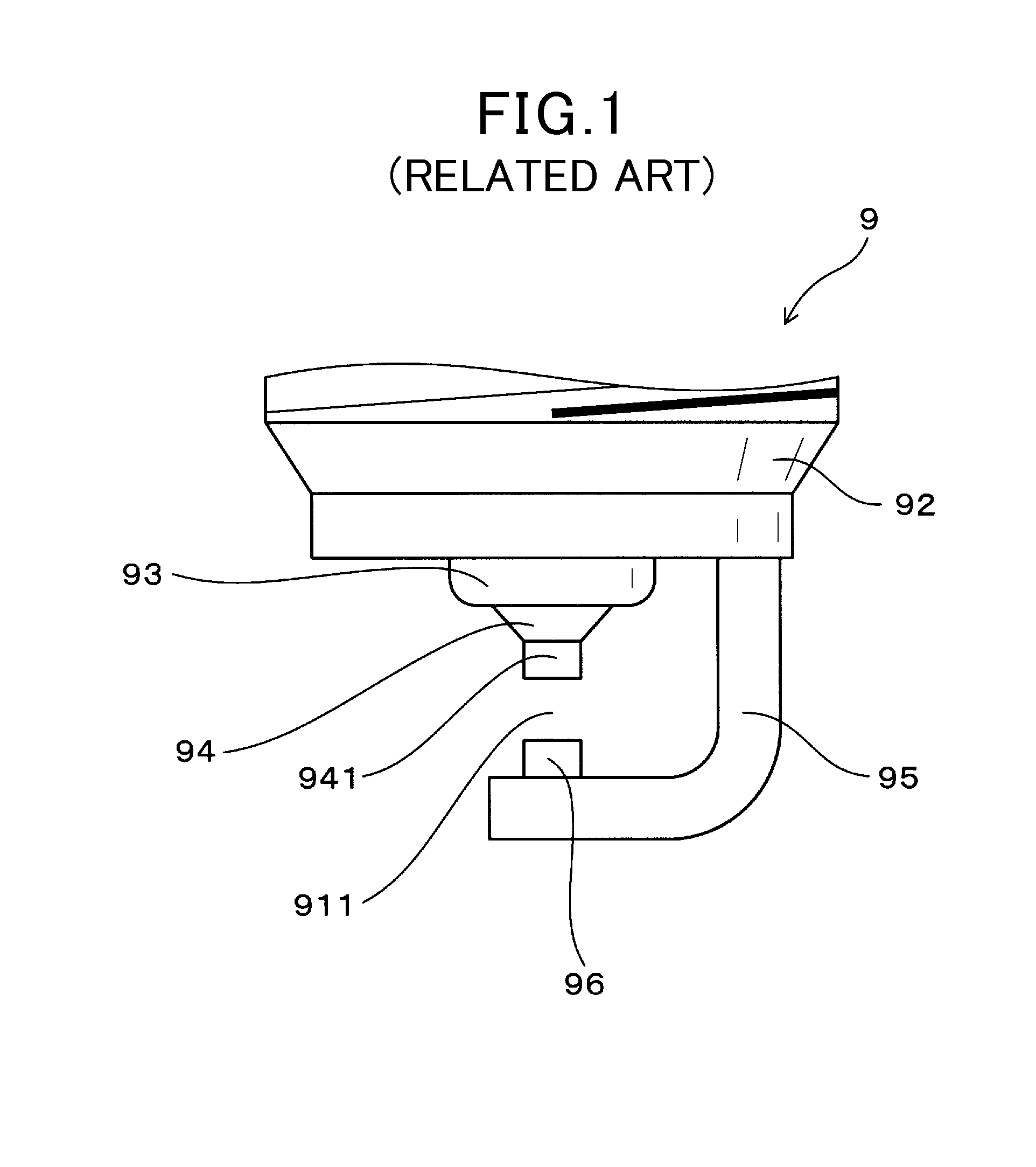
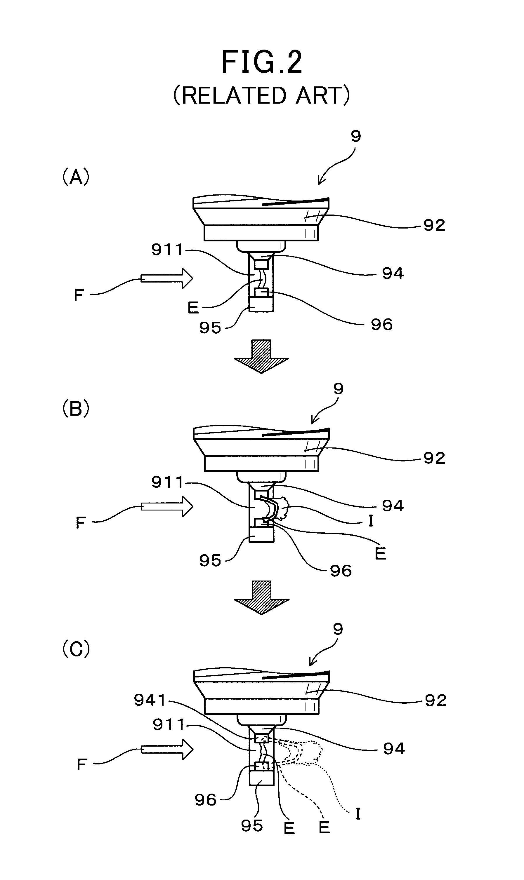
[0087]Specifically, in the present example, the following endurance test was conducted to measure the number of times of re-discharges of each of the spark plugs of Specimens 1 to 17 shown in Experimental Example 1 (Table 1) and confirm whether the number of times of re-discharges is reduced compared to the number of times of re-discharges of the spark plug 9 (see FIG. 1) shown in Experimental Example 1.

[0088]The conditions of the targets of evaluation (Specimens 1 to 17) were similar to those in Experimental Example 1 described above. Further, three sample spark plugs were prepared for each of Specimens 1 to 17.

[0089]The following endurance test was conducted using these specimens.

[0090]In conducting the endurance test, the spark plugs of Specimens 1 to 17 were loaded on a test device resembling to the combustion chamber 80, creating a nitrogen atmo...


PUM


Abstract

A spark plug is provided, which includes a housing, an insulation porcelain, a center electrode, a main ground electrode, a first sub ground electrode and a second sub ground electrode. The first and second sub ground electrode are arranged being opposed to each other. Requirements of Hs1<Hc+Gm, Gm<Gs1+Gg, Gm<Gs2+Gg, Hs2≧Hs1 and Hc<Hs2 are satisfied, where Hc is the length of projection of the center electrode, Gm is the size of the main gap, Hs1 is the length of projection of the first sub ground electrode, Hs2 is the length of projection of the second sub ground electrode, Gs1 is the length of the first sub gap in the radial direction of the plug, Gs2 is the length of the second sub gap in the radial direction of the plug, and Gg is the distance between an outer peripheral edge portion and an inner peripheral edge portion of a porcelain tip portion in the radial direction of the plug.

Description

TECHNICAL FIELD[0001]The present invention relates to a spark plug for an internal combustion engine and a mounting structure for the spark plug, the spark plug being used for passenger cars, automatic two-wheeled vehicles, cogeneration systems, gas pressure pumps or the like.BACKGROUND TECHNIQUE[0002]FIG. 1 shows a conventionally used spark plug 9 for an internal combustion engine. For example, the spark plug 9 is used as a means for igniting an air-fuel mixture introduced into a combustion chamber of an internal combustion engine such as of a passenger car.[0003]The spark plug 9 includes a center electrode 94 and a ground electrode 95. The ground electrode 95 has an end fixed to a housing 92, while being crooked to bring the other end to a position facing the center electrode 94, to form a spark discharge gap 911 in relation to the center electrode 94. The ground electrode 95 is provided with a projection portion 96 which is projected toward the spark discharge gap 911 (see Patent...

Claims


Application Information

Patent Timeline
Patent Type & Authority Applications(United States)
IPC IPC(8): F02P15/00
CPCF02P15/00F02P13/00H01T13/32H01T13/467H01T13/14
Inventor HANASHI, KEN
Owner DENSO CORP
Why Eureka
Try Eureka