
Jig assembly, laminating apparatus, and laminating method using the laminating apparatus

a technology of laminating apparatus and laminating machine, which is applied in the direction of auxillary welding device, identification means, instruments, etc., can solve the problems of limited applications and uses, and achieve the effect of preventing the formation of creases

Active Publication Date: 2014-10-09
SAMSUNG DISPLAY CO LTD +1
View PDF5 Cites 17 Cited by
  • Summary
  • Abstract
  • Description
  • Claims
  • Application Information

AI Technical Summary

Benefits of technology

The present invention provides a jig assembly that prevents creing during lamination of plates. This improves productivity and reduces defects, resulting in better quality products. The invention also includes a laminating apparatus and method that increase efficiency and productivity.

Problems solved by technology

Since these conventional LCDs, PDPs, and OLEDs use a glass substrate, they are lacking in flexibility and thus have limited applications and uses.

Method used

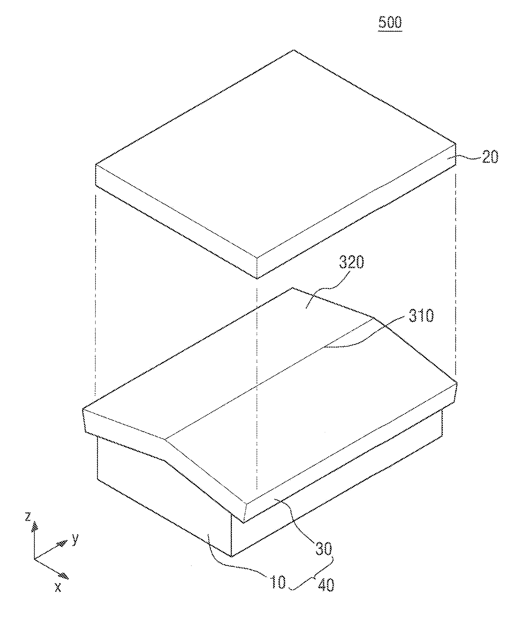
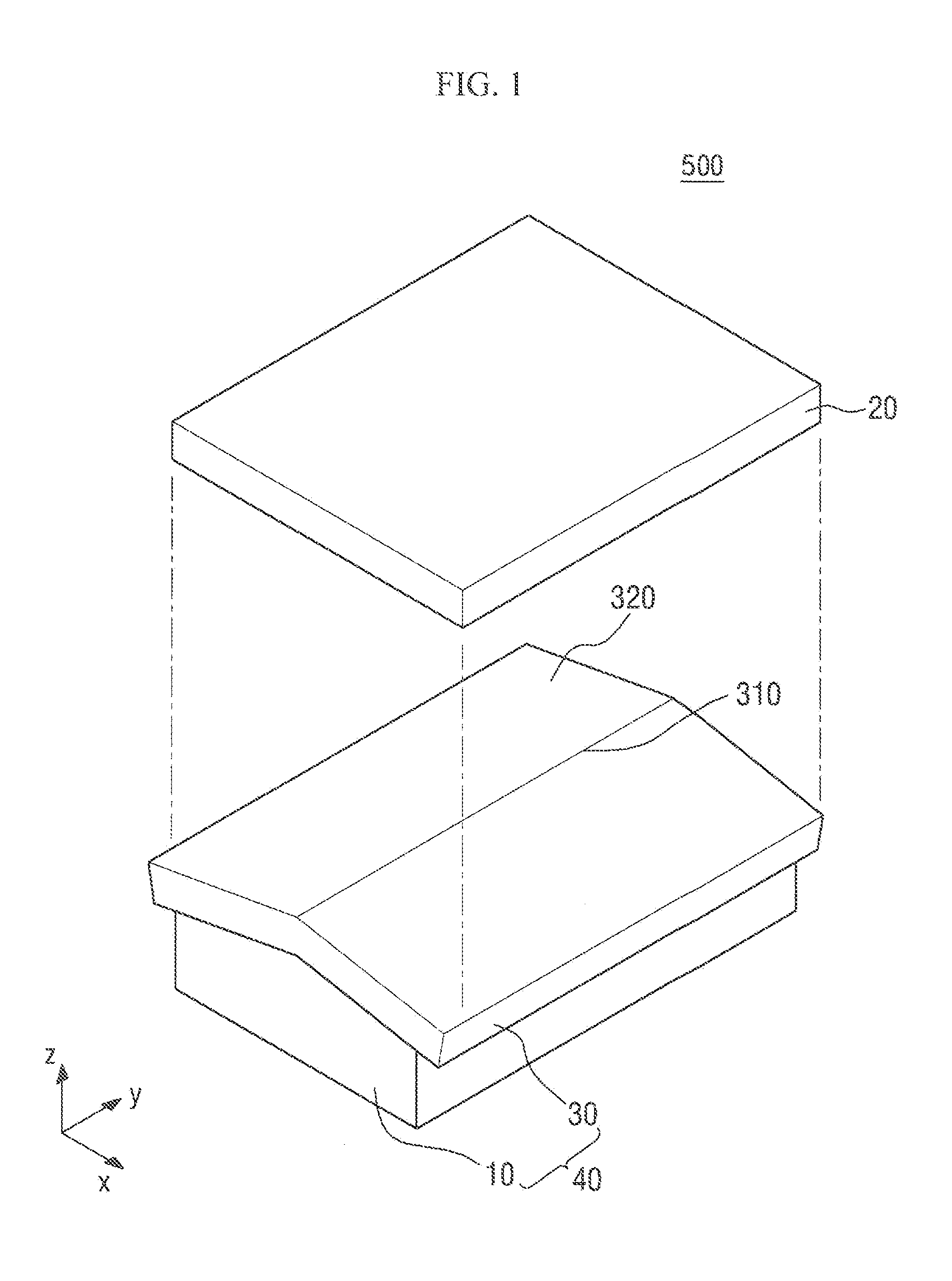
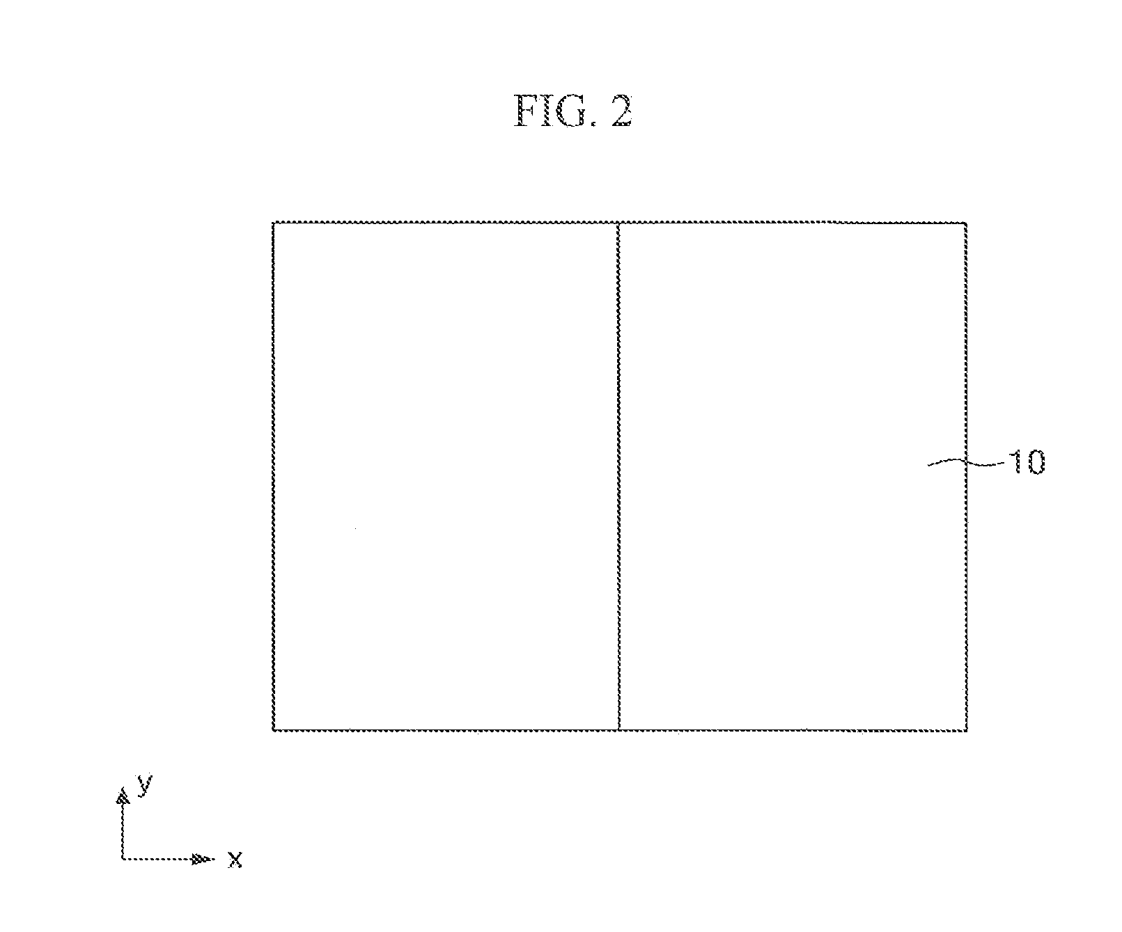

Image

  • Jig assembly, laminating apparatus, and laminating method using the laminating apparatus
  • Jig assembly, laminating apparatus, and laminating method using the laminating apparatus
  • Jig assembly, laminating apparatus, and laminating method using the laminating apparatus

Examples


Embodiment Construction

[0033]The aspects and features of the present invention and methods for achieving the aspects and features will be apparent by referring to the embodiments to be described in detail with reference to the accompanying drawings. However, the present invention is not limited to the embodiments disclosed hereinafter, but can be implemented in diverse forms. The matters defined in the description, such as the detailed construction and elements, are nothing but specific details provided to assist those of ordinary skill in the art in a comprehensive understanding of the invention, and the present invention is only defined within the scope of the appended claims.

[0034]The term “on” that is used to designate that an element is on another element or located on a different layer or a layer includes both a case where an element is located directly on another element or a layer and a case where an element is located on another element via another layer or still another element. In the entire de...


PUM

PropertyMeasurementUnit
thicknessaaaaaaaaaa
thicknessesaaaaaaaaaa
shapeaaaaaaaaaa

Abstract

Provided are laminating apparatus and method. A laminating apparatus includes a jig assembly, which includes the first jig and an elastic member, and a second jig. A laminating method includes placing a first plate on a jig assembly, placing a second plate on a second jig which is placed to face the first jig, bringing the second plate into contact with the adhesive layer by making the jig assembly and the second jig approach each other, and, attaching the first plate and the second plate to each other by making the jig assembly and the second jig approach closer to each other. The jig assembly includes a first jig and an elastic member which comprises a top portion and sloping portions sloping downward from the top portion. An adhesive layer is disposed between the first plate and the second plate.

Description

CLAIM OF PRIORITY[0001]This application claims priority from Korean Patent Application No. 10-2013-0036497 filed on Apr. 3, 2013 in the Korean Intellectual Property Office, the disclosure of which is incorporated herein by reference in its entirety.BACKGROUND OF THE INVENTION[0002]1. Field of the Invention[0003]The present invention relates to a jig assembly, a laminating apparatus, and a laminating method using the laminating apparatus.[0004]2. Description of the Related Art[0005]Currently, the display market is rapidly being dominated by flat panel displays (FPDs) that can be easily made to have a large area and can be made thinner and lighter.[0006]Examples of the FPDs include liquid crystal displays (LCDs), plasma display panels (PDPs), and organic light-emitting displays (OLEDs). Since these conventional LCDs, PDPs, and OLEDs use a glass substrate, they are lacking in flexibility and thus have limited applications and uses.[0007]In this regard, flexible displays that can be ben...

Claims


Application Information

Patent Timeline
Patent Type & Authority Applications(United States)
IPC IPC(8): B29C65/52
CPCB29C65/52B30B15/062B32B37/10B32B2037/1253B32B2310/0831B32B2457/20G02F1/1303G02F1/133305B32B37/00G09F9/00G09F9/30B29C66/8161
Inventor SON, YANG HANKIM, JONG HWANKIM, YOUNG SIKLEE, KYUNG SU
Owner SAMSUNG DISPLAY CO LTD
Learn More