Method of increasing fracture network complexity and conductivity

Inactive Publication Date: 2014-10-09
BAKER HUGHES INC
View PDF6 Cites 37 Cited by
  • Summary
  • Abstract
  • Description
  • Claims
  • Application Information

AI Technical Summary

Benefits of technology

[0026](a) pumping a first fluid of low viscosity into the formatio

Problems solved by technology

After the viscosity of the fluid has been reduced, complete removal of the polymer is often difficult, often times resulting in residual polymer being left on the face of the formation and within the proppant pack.
This causes clogging of the pores of the formation and proppant pack.
Slickwater fluids typically do not contain a viscoelastic surfactant or viscosifying polymer but do contain a sufficient amount of a friction reducing agent to minimize tubular friction pressures.
In some shale formations, an excessively long primary fracture often results along the minimum stress orientation.
In most instances, primary fractures dominate and secondary fractures are limited.
Production of hydrocarbons from the fracturing network created by such treatments is limited by the low SRV.
Slickwater fracturing more commonly in shale formations create complex fracture networks near the wellbore and are generally considere

Method used


Image

  • Method of increasing fracture network complexity and conductivity
  • Method of increasing fracture network complexity and conductivity
  • Method of increasing fracture network complexity and conductivity

Examples


embodiment 500

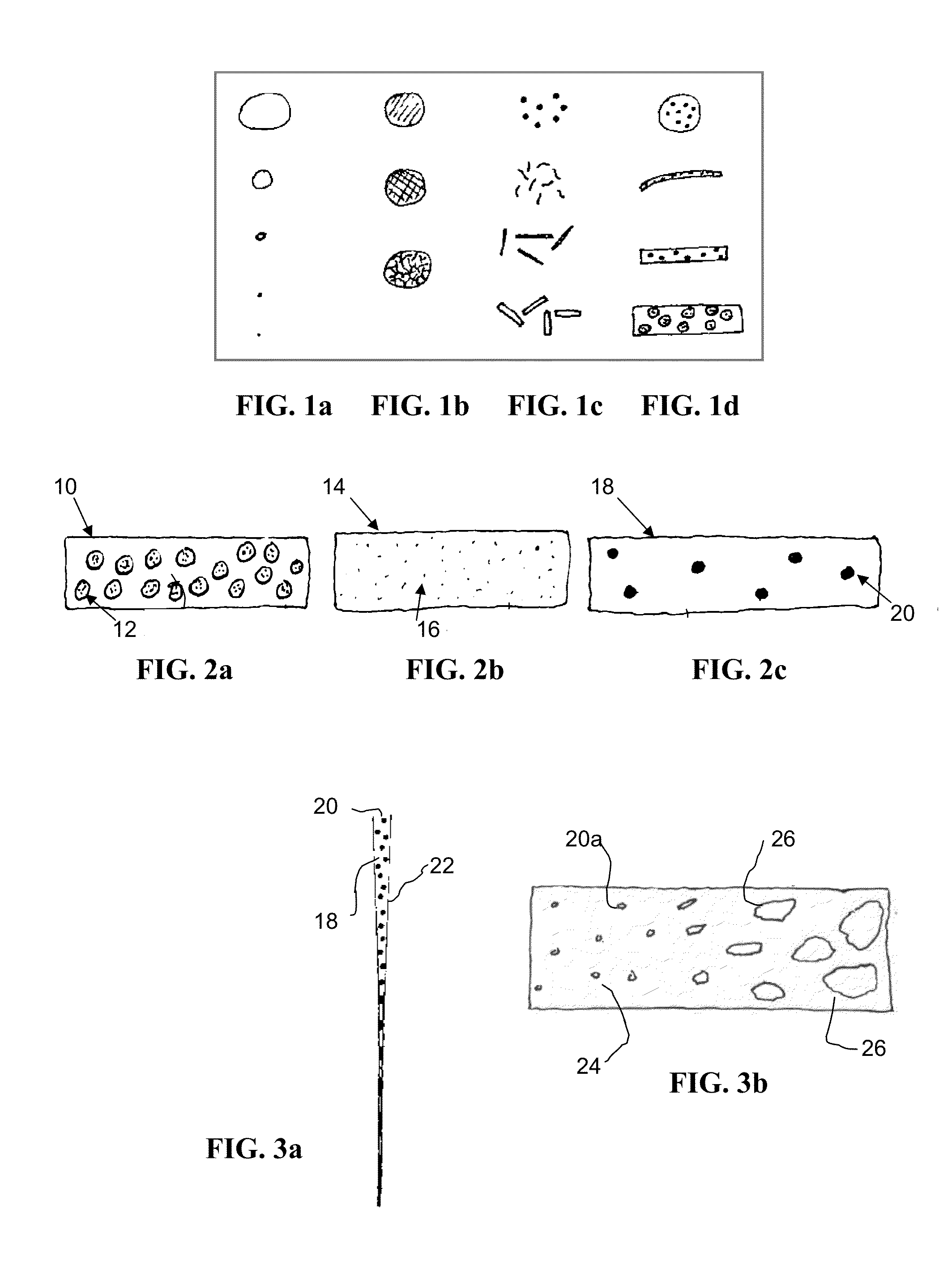
[0056]The size of the viscous material will typically vary depending on the width characteristic of the hydraulic fractures created within lower permeability reservoirs. For instance, the viscous material may have an average particle size from about 500 nm to about 50 cm, in one non-limiting embodiment 500 nm to about 30 mm, alternatively from about 1 μm to about 4 mm, and in another non-limiting embodiment about 10 μm to about 1 mm.

[0057]During pumping, the viscous material effectively retains its size and shape within the second fluid and appears as discrete tiny masses with near zero shear rate viscosity in the low viscosity fluid. The tiny high viscosity material in the second fluid, in one non-limiting embodiment, is thus highly elastic and deformable and resists fluid-shear-induced fragmentation during pumping. Depending on the size of the viscous material, the second fluid may behave like the first fluid as it flows into and through the initial portion of the primary fracture...

embodiment 1000

[0079]While the viscosity of the second fluid and first fluid may be substantially the same, the viscous material is at least 1,000 times more viscous than the first fluid, and typically is more than 100,000 times more viscous than the first fluid at 0.01 sec−1 shear rate at 80° F. (27° C.). The ratio in viscosity (measured at 0.01 sec−1 and 80° F. ((27° C.)), Vr, of the viscous material to the first fluid may be designed to achieve the fracturing and production purposes of the methods described herein. In one non-limiting embodiment, for example, Vr is 100 or greater, in one non-limiting embodiment 1000 or greater, alternatively is 10,000 or greater, and in a different non-limiting embodiment is 100,000 or greater.

[0080]The integrity of the viscous material to retain its size and shape during shear when being pumped downhole may be dependent on the viscosity, size, shape, density and other properties of the viscous material. While the viscous material may be of larger sizes fluid d...


PUM


Abstract

A complex fracture network within a hydrocarbon-bearing subterranean formation is created by first pumping a first fluid into the formation to create or enlarge a primary fracture and then pumping a second fluid into the formation wherein the second fluid contains a viscous material and the first fluid. By diverting the flow of the second flow, a secondary fracture is created having a directional orientation distinct from the directional orientation of the primary fracture.

Description

[0001]This application claims the benefit of U.S. patent application 61 / 809,187, filed on Apr. 5, 2013, herein incorporated by reference.FIELD OF THE DISCLOSURE[0002]Fracture network complexity within a subterranean formation may be created by pumping a low viscosity fluid into the formation followed by a low viscosity fluid containing independent small masses of viscous material. Stimulated rock volume (SRV) of the formation is increased with the complex fracture network created in the formation.BACKGROUND OF THE DISCLOSURE[0003]Hydraulic fracturing is widely used to create high-conductivity communication with a large area of a subterranean formation, thereby allowing for an increased rate of oil and gas production. The stimulation process enhances the permeability of the formation in order that entrapped oil or gas may be produced.[0004]During hydraulic fracturing of ultra-low permeability formations (i.e. such as less than 0.1 md), a fracturing fluid is pumped at high pressures a...

Claims


Application Information

Patent Timeline
IPC IPC(8): E21B43/267
CPCE21B43/267C09K8/62C09K8/80E21B43/26
Inventor CREWS, JAMES B.LI, CHUNLOU
Owner BAKER HUGHES INC
Why Eureka
Try Eureka