Static Weight Energy Production Apparatus

Inactive Publication Date: 2014-10-09
BARBIERO COSIMO
View PDF3 Cites 17 Cited by
  • Summary
  • Abstract
  • Description
  • Claims
  • Application Information

AI Technical Summary

Benefits of technology

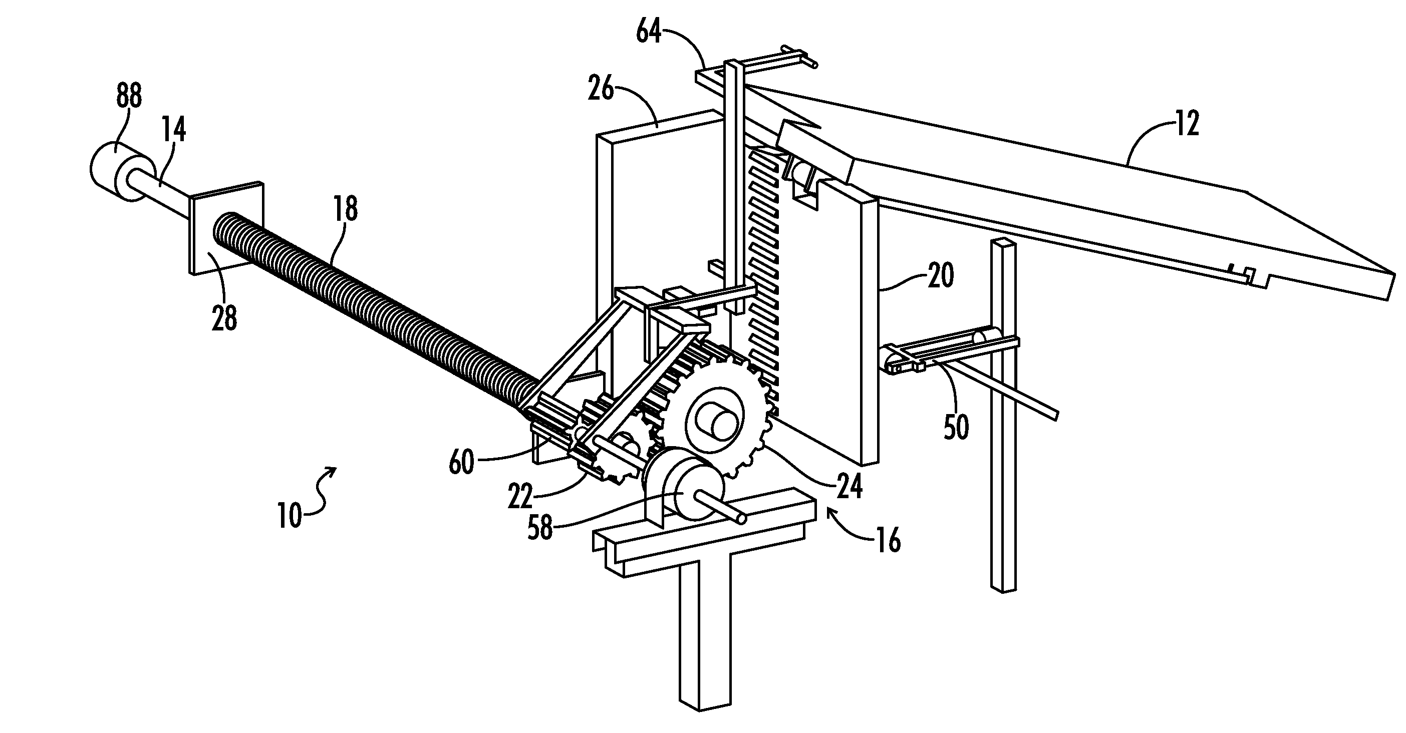
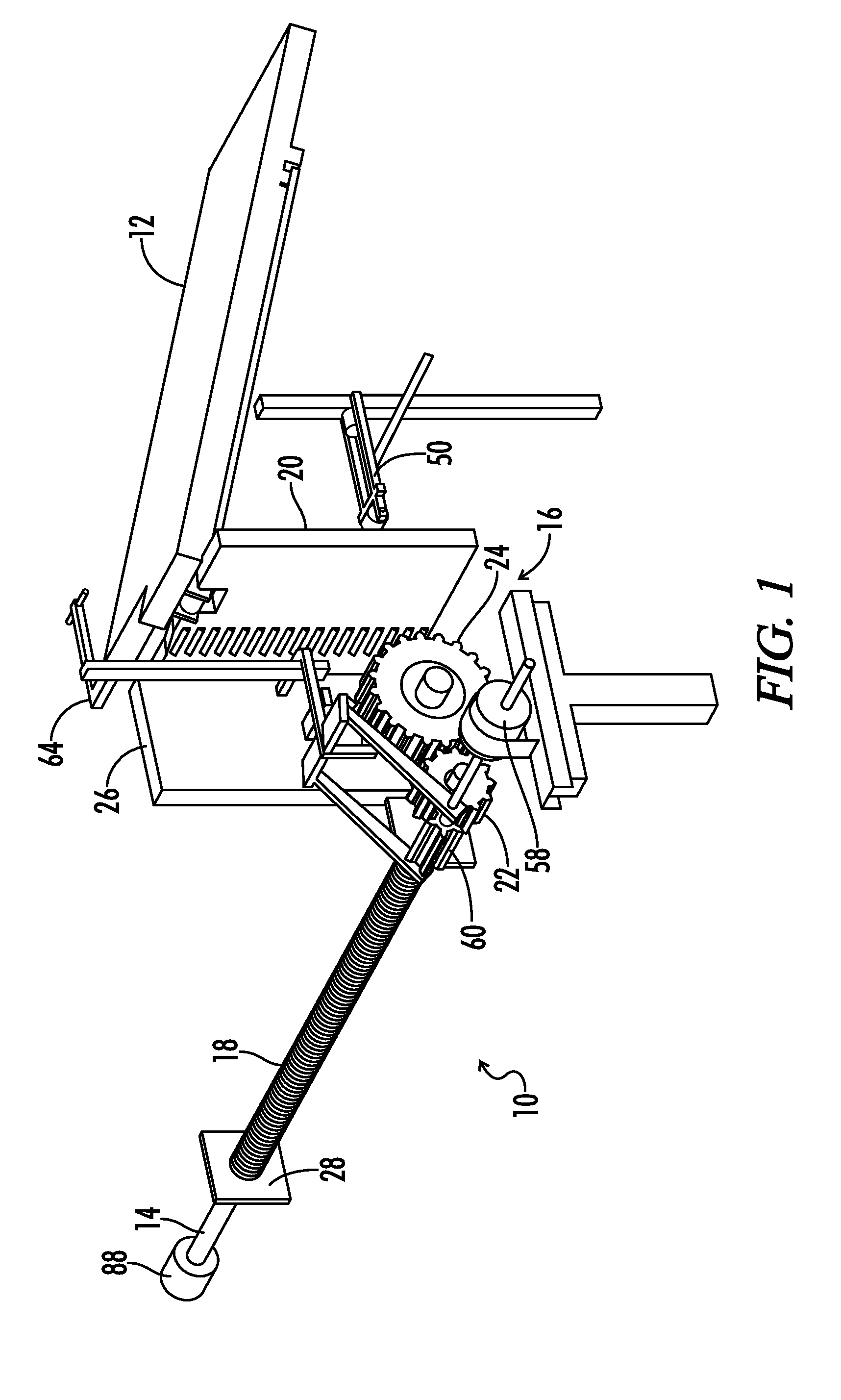
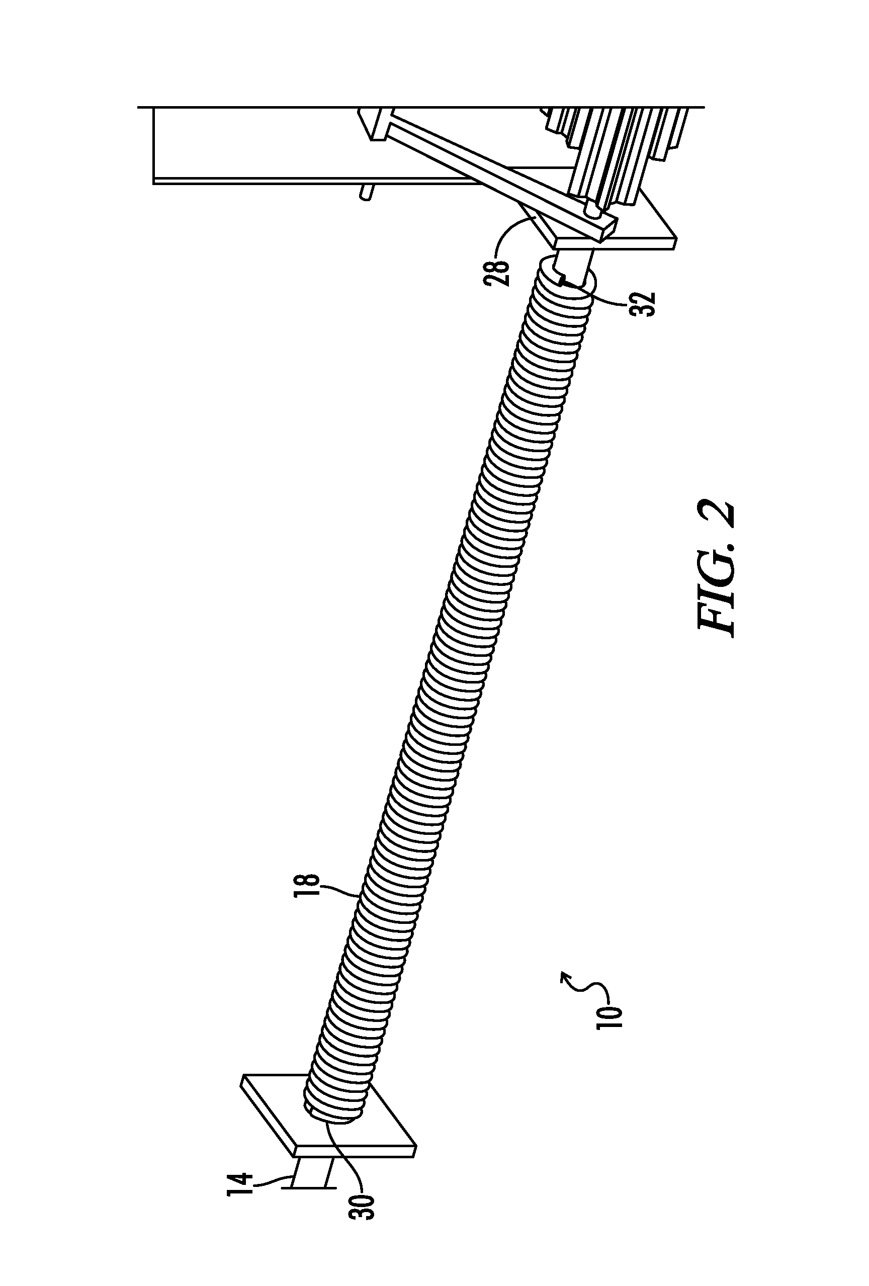
[0010]One aspect of the present invention is an energy production apparatus having a weight bearing member that can alternate between an upper and lower position. The apparatus includes a drive shaft and a gear system. The gear system can be connected to the drive shaft and the weight bearing member. The gear system is positioned to rotate the drive shaft as a load is placed on the weight bearing member and the weight bearing member moves from the upper position to the lower position. A torsion spring can be connected to the drive shaft. The torsion spring can be positioned to wind as the weight bearing member moves from the upper position to the lower position. A return member can be configured to return the weight bearing member to the upper position once the load is removed from the weight bearing member. A locking member can selectively engage the gear system. The locking member can prevent the torsion spring from unwinding when the locking member is engaged with the gear system. In some embodiments, the locking member includes a pawl and ratchet system, such that when the pawl is engaged with the gear system, the gear system can be free to rotate in order to wind the torsion spring, but the gear system can be prevented from rotating in the op

Problems solved by technology

Thus these systems do not capture the significant gravitational potential energy of larger objects such cars or other vehicles.
These systems however, can only produce energy as the load is moving downward.
There is significant energy loss that occurs during the start-

Method used


Image

  • Static Weight Energy Production Apparatus
  • Static Weight Energy Production Apparatus
  • Static Weight Energy Production Apparatus

Examples


Embodiment Construction

[0028]While the making and using of various embodiments of the present invention are discussed in detail below, it should be appreciated that the present invention provides many applicable inventive concepts that is embodied in a wide variety of specific contexts. The specific embodiments discussed herein are merely illustrative of specific ways to make and use the invention and do not delimit the scope of the invention.

[0029]To facilitate the understanding of the embodiments described herein, a number of terms are defined below. The terms defined herein have meanings as commonly understood by a person of ordinary skill in the areas relevant to the present invention. Terms such as “a,”“an,” and “the” are not intended to refer to only a singular entity, but rather include the general class of which a specific example may be used for illustration. The terminology herein is used to describe specific embodiments of the invention, but their usage does not delimit the invention, except as...


PUM


Abstract

An energy production apparatus that includes a weight bearing member configured to alternate between an upper and lower position, and a drive shaft. A gear system can be connected to the weight bearing member and the drive shaft. The gear system can be positioned to rotate the drive shaft when a load is placed on the weight bearing member and the weight bearing member moves from the upper position to the lower position. A torsion spring can be connected to the drive shaft, the torsion spring positioned to wind as the weight bearing member moves to the lower position. A return member can be configured to return the weight bearing member to the upper position. A locking member can selectively engage the gear system, the locking member preventing the torsion spring from unwinding when engaged. A generator can be driven by the drive shaft as the torsion spring unwinds.

Description

CROSS-REFERENCES TO RELATED APPLICATIONS[0001]This application claims benefit of the following patent application(s) which is / are hereby incorporated by reference: Ramp Generator, Ser. No. 61 / 806,479, filed Mar. 29, 2013.[0002]A portion of the disclosure of this patent document contains material that is subject to copyright protection. The copyright owner has no objection to the reproduction of the patent document or the patent disclosure, as it appears in the U.S. Patent and Trademark Office patent file or records, but otherwise reserves all copyright rights whatsoever.STATEMENT REGARDING FEDERALLY SPONSORED RESEARCH OR DEVELOPMENT[0003]Not ApplicableREFERENCE TO SEQUENCE LISTING OR COMPUTER PROGRAM LISTING APPENDIX[0004]Not ApplicableBACKGROUND OF THE INVENTION[0005]The present invention relates generally to a static weight energy production apparatus that converts the static weight of a load into rotational motion that can be used for mechanical power or to power a generator. Suc...

Claims


Application Information

Patent Timeline
IPC IPC(8): F03G1/00F03G3/00
CPCF03G3/00F03G1/00F03G1/02F03G3/087F03G1/026
Inventor BARBIERO, COSIMO
Owner BARBIERO COSIMO
Why Eureka
Try Eureka