Telephoto lens system and electronic apparatus having the same
a technology of electronic equipment and lens system, which is applied in the field of telephoto lens system and electronic equipment having the same, can solve the problems of difficult lens processing for correcting spherical aberration or astigmatic field curvature, and achieve the effect of easy processing
- Summary
- Abstract
- Description
- Claims
- Application Information
AI Technical Summary
Benefits of technology
Problems solved by technology
Method used
Image
Examples
first embodiment
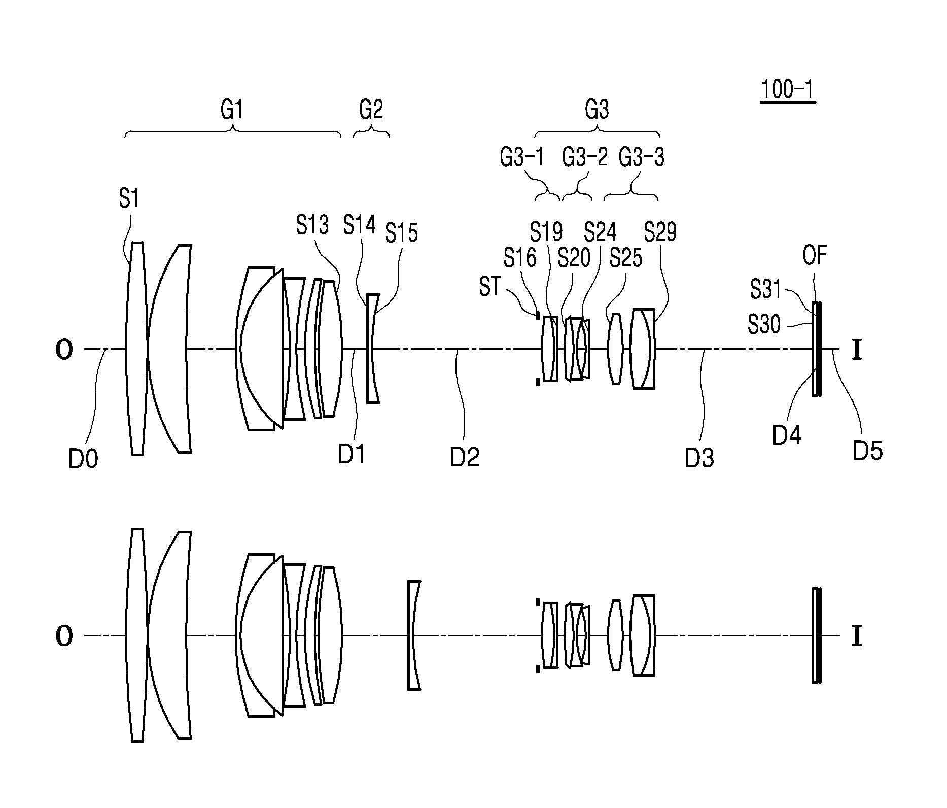
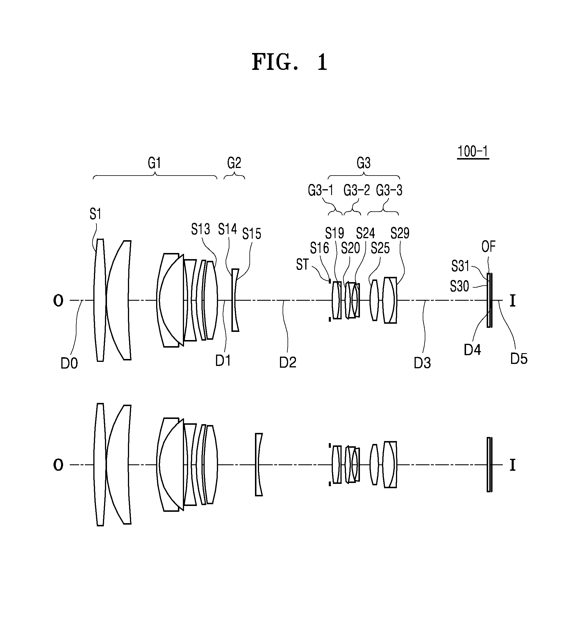
[0062]FIG. 1 illustrates a telephoto lens system 100-1 in relation to infinity and a near object distance according to a first embodiment. The following Table 1 shows design data of the first embodiment. Lens surface numbers are partially shown in FIG. 1.
TABLE 1Lens surfaceRDnNdvdZ-valueNoteobjinfinityD0S1467.10810.0001.4874970.440.1053First lens group G1S2−467.1080.200S390.94417.0001.4970081.610.2037S4395.62323.311S5125.5612.5401.6968055.460.2199S645.80019.0001.4970081.610.3696S7infinity3.500S8−182.9933.0001.8348142.720.2109S9130.7443.918S10120.8955.0001.7282528.320.0446S11180.6061.000S12180.60611.0001.4970081.610.2044S13−132.794D1S14infinity2.4001.4874970.440.1360Second lens group G2S1588.416D2S16(ST)infinity2.000(3-1)-th lens group G3-1S17106.0166.0001.7015441.150.1882S18−55.8401.5001.7618226.610.1131S19−711.3003.306S20121.0634.0001.8466623.780.1548(3-2)-th lens group G3-2S21−70.8191.0001.6779055.520.3040S2231.5494.500S23−53.2111.0001.6968055.460.1591S24185.5139.236S2566.7057.000...
second embodiment
[0065]FIG. 3 illustrates a telephoto lens system 100-2 in relation to infinity and a near object distance according to a second embodiment, and the following Table 3 shows design data of the second embodiment.
TABLE 3Lens surfaceRDnNdvdZ-valueNoteobjinfinityD0S1448.07110.0001.4874970.440.1086First lens group G1S2−448.0710.100S3101.44719.3001.4970081.610.3149S4−292.7900.143S5−320.6285.3001.7725049.620.1143S6541.76049.323S792.0912.5001.6968055.460.1584S845.74817.3001.4970081.610.3124S9529.597D1S10443.5184.5301.8466623.780.1061Second lens group G2S11−152.1311.5001.8348142.720.2114(AF group)S1285.162D2S13(ST)infinity3.850(3-1)-th lens group G3-1S1434.8238.0001.5688356.040.2153S15448.0712.0001.8466623.780.1780S1635.8374.240S17138.7265.3001.5168064.200.0983S18−138.7263.018S19−126.1983.8101.8466623.780.1520(3-2)-th lens group G3-2S20−32.4851.0001.7495035.040.3153S2159.13020.759S2287.5616.0001.8466623.780.0840(3-3)-th lens group G3-3S23−1000.000D3S24infinity4.0001.5168064.20S25infinityD4imgi...
third embodiment
[0068]FIG. 5 illustrates a telephoto lens system 100-3 in relation to infinity and a near object distance according to a third embodiment, and the following Table 5 shows design data of the third embodiment.
TABLE 5Lens surfaceRDnNdvdZ-valueNoteobjinfinityD0S1700.0009.0001.4874970.440.0711First lens group G1S2−700.0000.150S3112.04419.5001.4970081.610.3007S4−290.7881.300S5−303.7995.0001.7725049.620.2821S6109.9549.559S7100.26010.0001.4970081.610.1479S8280.9360.100S997.85710.0001.8466623.780.1643S10336.17627.661S1168.96010.4801.5688356.040.2684S12−405.4562.0001.8466623.780.3125S1349.4953.575S1483.1286.0001.8830040.800.1059S15230.897D1S16333.7954.3001.8466623.780.0623Second lens group G2S17−428.4961.2101.7495035.040.1936(AF group)S1865.262D2S19150.9862.0001.8466623.780.1723(3-1)-th lens group G3-1S2039.8127.9501.5814440.890.3167S21−118.3962.116S22−274.4435.0001.8466623.780.2101(3-2)-th lens group G3-1S23−38.5901.0001.8061033.270.3793S2467.0903.104S25104.5994.0001.8466623.780.0833(3-3)-th...
PUM
 Abstract
Description
Claims
Application Information
 - R&D
- Intellectual Property
- Life Sciences
- Materials
- Tech Scout
- Unparalleled Data Quality
- Higher Quality Content
- 60% Fewer Hallucinations
Browse by: Latest US Patents, China's latest patents, Technical Efficacy Thesaurus, Application Domain, Technology Topic, Popular Technical Reports.
© 2025 PatSnap. All rights reserved.Legal|Privacy policy|Modern Slavery Act Transparency Statement|Sitemap|About US| Contact US: help@patsnap.com


