Server cooling system without the use of vapor compression refrigeration

a server cooling and refrigeration technology, applied in the field of data center cooling, can solve the problems of large amount of power and significant energy consumption of current systems using vapor compression refrigeration

Active Publication Date: 2014-10-09
IBM CORP
View PDF5 Cites 22 Cited by
  • Summary
  • Abstract
  • Description
  • Claims
  • Application Information

AI Technical Summary

Problems solved by technology

Current systems using vapor compression refrigeration require significant amounts of energy to operate.
However, these systems still require large amount of power to operate the pump and fans.

Method used


Image

  • Server cooling system without the use of vapor compression refrigeration
  • Server cooling system without the use of vapor compression refrigeration
  • Server cooling system without the use of vapor compression refrigeration

Examples


second embodiment

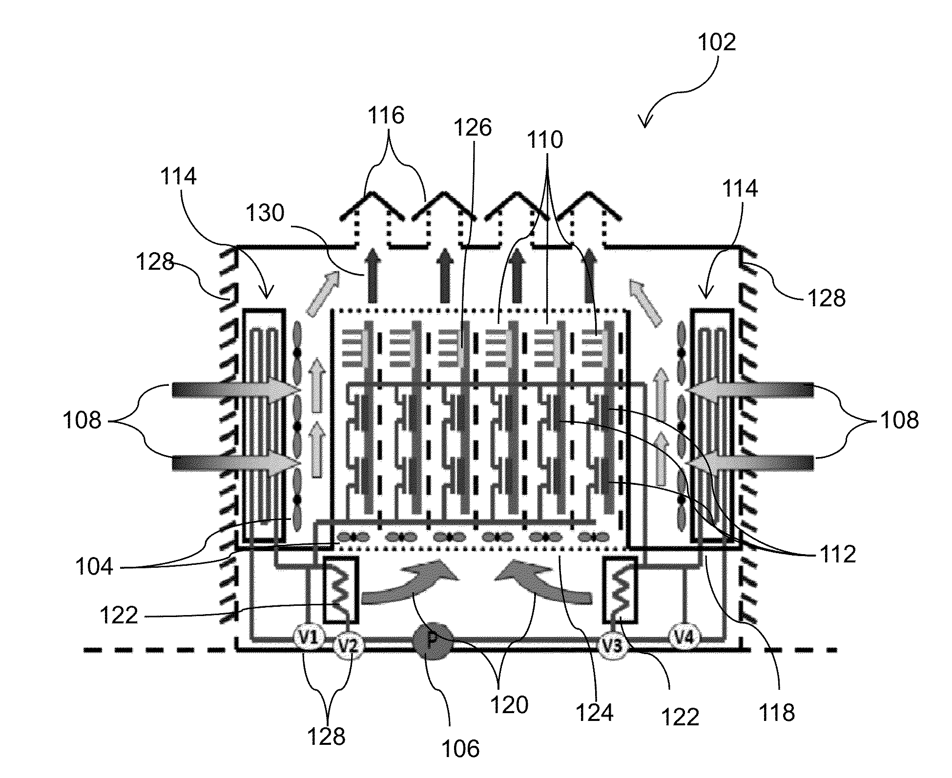
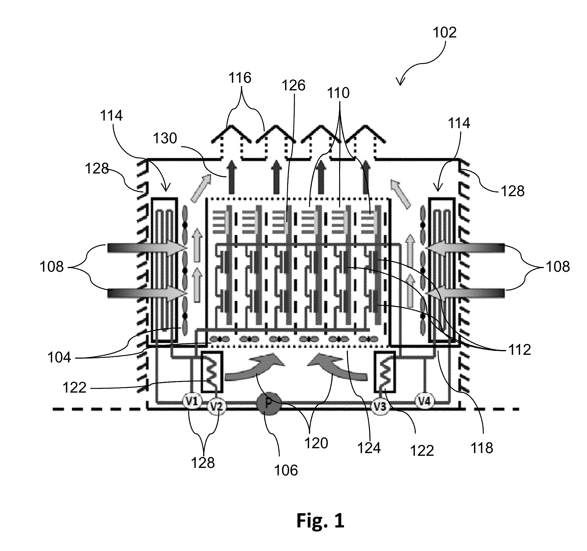
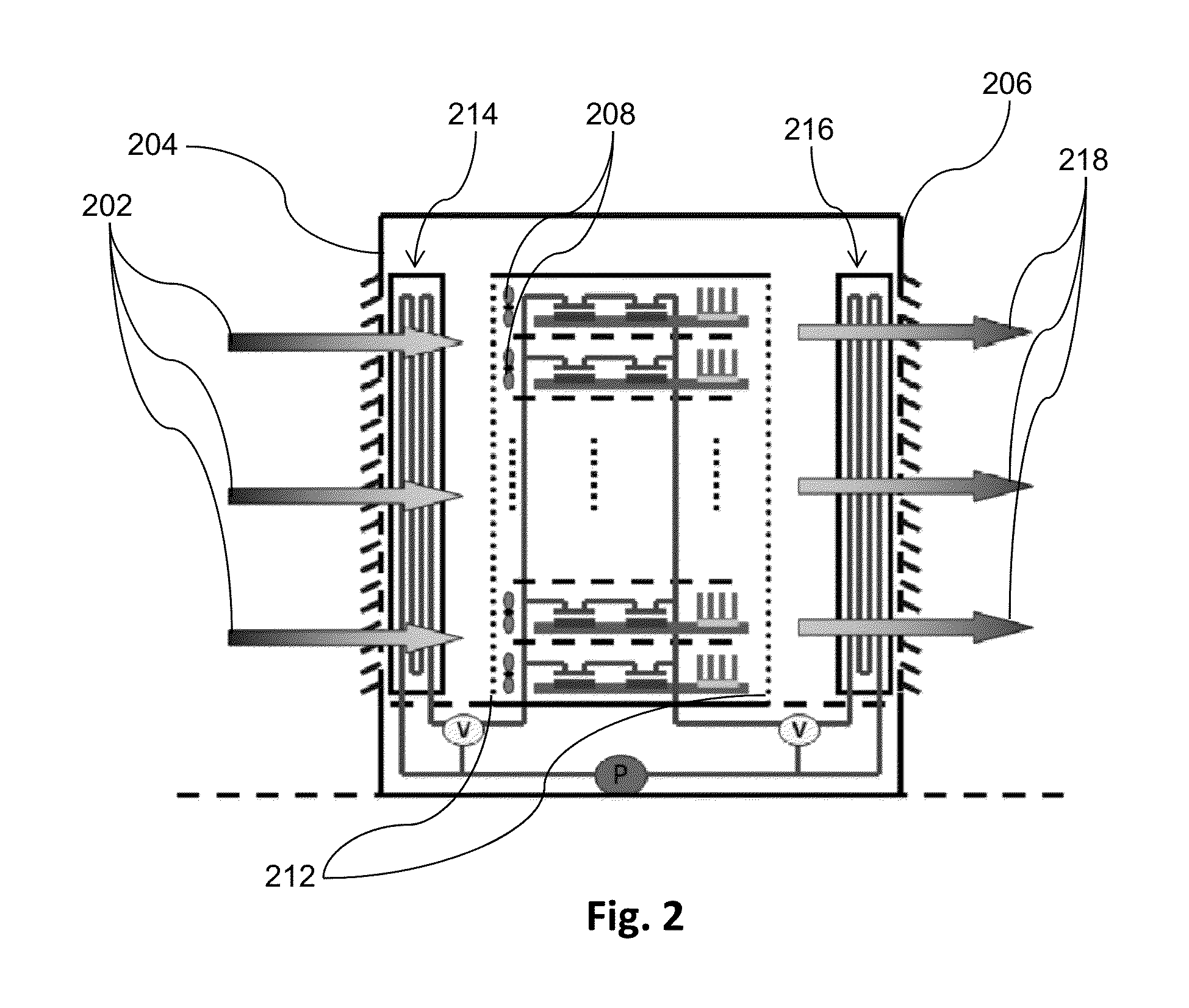
[0023]FIG. 2 shows a cross-sectional view of the present invention. According to this embodiment the outdoor ambient air 202 would flow in through an entrance sidewall 204 and heated air 218 would exit through an exit side wall 206. The airflow is produced by fans 208 inside the server racks 210. The server rack 212 in this embodiment can have its front and rear surfaces perforated to facilitate airflow through the rack.

[0024]In this embodiment, a first heat exchanger 214 is placed next to the entrance sidewall 204 and a second heat exchanger 216 is placed next to the exit sidewall 206. The server racks are positioned in between the heat exchangers 214, 216. In one embodiment, there are no fans next to the heat exchangers. The fans in the server rack 210 thus create the airflow necessary to cool the heat exchangers.

[0025]Heated liquid exiting the server flows through the first heat exchanger 214. If the liquid is required to be cooled further it is passed through the second heat exc...

third embodiment

[0026]FIG. 3 shows a cross-sectional view of the present invention. This embodiment is similar to the embodiment in FIG. 2, the difference being that the airflow is produced by fans 302 outside of the server rack 304 next to the heat exchanger 306. This allows for larger fans, having, for example, a diameter above 200 mm. Larger fans are advantageous because they create airflow more efficiently.

[0027]FIG. 4 shows an example cooling schematic for a server circuit board 402. The components 404 that generate high amount of heat are cooled by liquid coolant and the components 406 generating less heat are cooled by air with the use of heat sinks.

[0028]FIG. 5 shows a method 502 for cooling server centers in accordance with one embodiment of the present invention. The method includes an air introduction step 504. During step 504 outdoor ambient air can be passed into the entrance of the server center through opening in the sidewalls. Airflow into the server center can be controlled by the ...


PUM


Abstract

A system, method, and computer product for cooling a server center without the use of vapor compression refrigeration. An example embodiment involves using outdoor ambient air to cool first server components directly and to cool heat exchanges containing liquid used to cool second server components.

Description

BACKGROUND[0001]This invention relates to data center cooling, and more particularly to a system and a method to increase cooling efficiency without the use of vapor compression refrigeration.[0002]The energy consumed by data centers has doubled over the past six year and is predicted to keep increasing at the same rate. Up to forty percent of the power consumed by data centers is used to cool them to an optimum operating temperature. Current systems using vapor compression refrigeration require significant amounts of energy to operate.[0003]Recent trends to reduce energy have resulted in systems using only liquid circulation to transfer the heat out of the server. These systems pump the liquid containing heat from the servers through outdoor heat exchangers that allow the heat to dissipate into the outdoor air. The cool liquid is circulated back into to server where it is used to cool the air circulating in the server and to directly cool server components. However, these systems s...

Claims


Application Information

Patent Timeline
Patent Type & Authority Applications(United States)
IPC IPC(8): H05K7/20
CPCH05K7/2079H05K7/20745
Inventor CHAINER, TIMOTHY J.PARIDA, PRITISH R.
Owner IBM CORP
Why Eureka
Try Eureka