
Method of optimizing and customizing rotor blade structural properties by tailoring large cell composite core and a rotor blade incorporating the same

a technology of composite core and rotor blade, which is applied in the field of composite rotor blade, can solve the problems of increasing manufacturing costs and considerable integration effor

Active Publication Date: 2014-10-09
BELL HELICOPTER TEXTRON INC
View PDF3 Cites 16 Cited by
  • Summary
  • Abstract
  • Description
  • Claims
  • Application Information

AI Technical Summary

Benefits of technology

The patent text describes a composite rotor blade design that aims to improve structural efficiency and decrease manufacturing costs. The technical effects of this design include a simplified manufacturing process and a more integrated structural load path between the spar member and the rest of the rotor blade body and skins. The method of manufacturing the tailored core of the rotor blade is also described in detail. Overall, the patent text provides a solution for integrating structural load paths and reducing manufacturing costs for rotor blades.

Problems solved by technology

However, a spar member must typically be separately cured prior to assembly with the other rotor blade members, which can increase manufacturing costs.
Further, spar members are only part of the rotor blade body, thus considerable effort must be made to integrate structural load paths between the spar member and the rest of the rotor blade body and skins.

Method used


Image

  • Method of optimizing and customizing rotor blade structural properties by tailoring large cell composite core and a rotor blade incorporating the same
  • Method of optimizing and customizing rotor blade structural properties by tailoring large cell composite core and a rotor blade incorporating the same
  • Method of optimizing and customizing rotor blade structural properties by tailoring large cell composite core and a rotor blade incorporating the same

Examples


Embodiment Construction

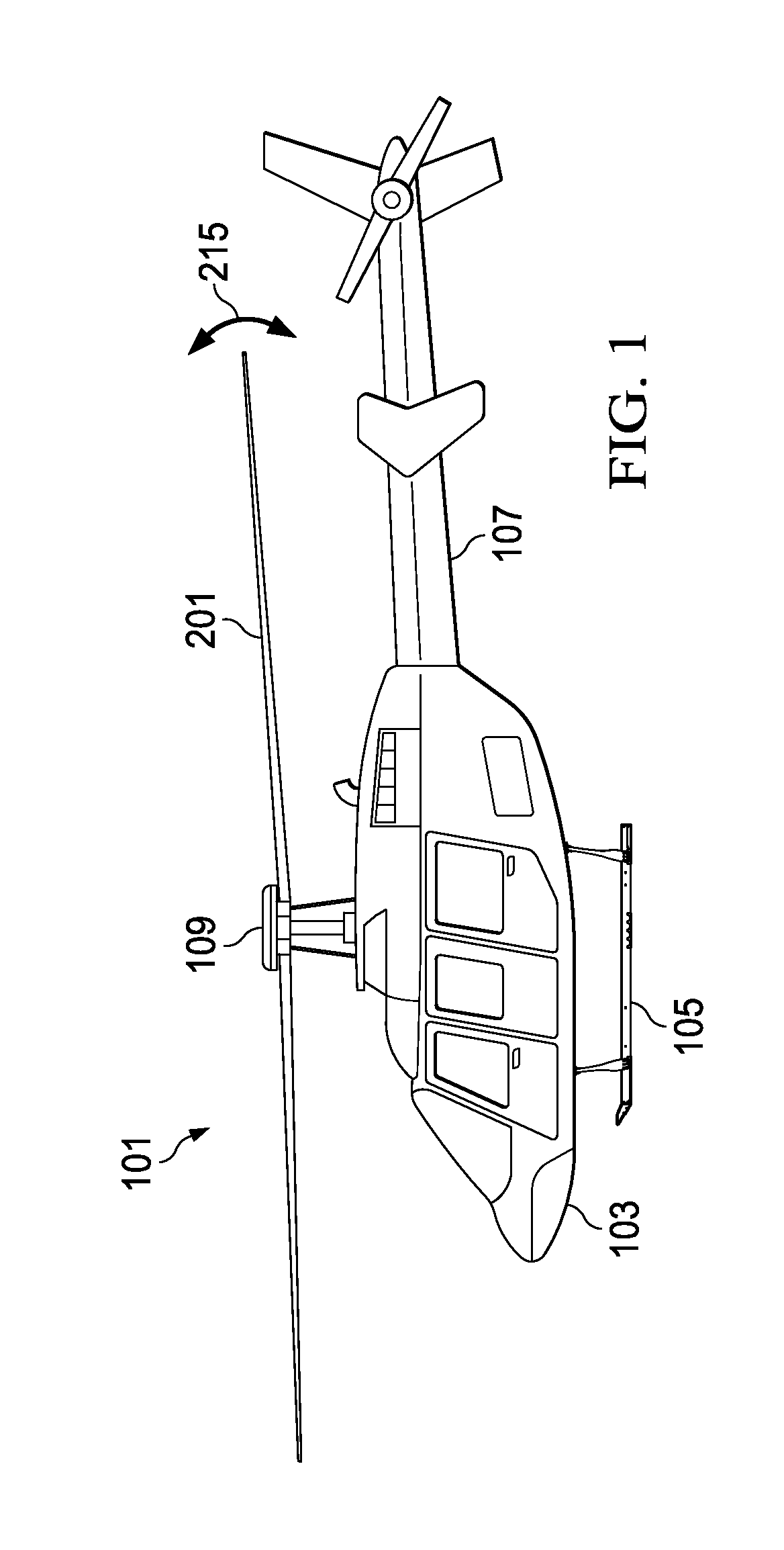
[0024]Illustrative embodiments of the apparatus and method are described below. In the interest of clarity, all features of an actual implementation may not be described in this specification. It will of course be appreciated that in the development of any such actual embodiment, numerous implementation-specific decisions must be made to achieve the developer's specific goals, such as compliance with system-related and business-related constraints, which will vary from one implementation to another. Moreover, it will be appreciated that such a development effort might be complex and time-consuming but would nevertheless be a routine undertaking for those of ordinary skill in the art having the benefit of this disclosure.

[0025]In the specification, reference may be made to the spatial relationships between various components and to the spatial orientation of various aspects of components as the devices are depicted in the attached drawings. However, as will be recognized by those ski...


PUM

PropertyMeasurementUnit
centrifugal forceaaaaaaaaaa
angleaaaaaaaaaa
thicknessaaaaaaaaaa

Abstract

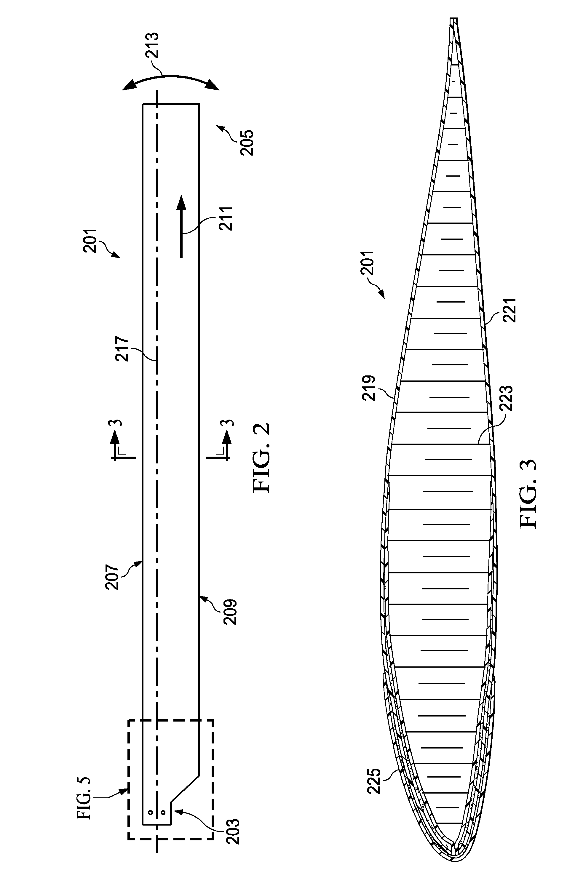
An airfoil member can have a root end, a tip end, a leading edge, and a trailing edge. The airfoil member can include an upper skin, a lower skin, and a composite core member having a plurality of cells, an upper surface network of the cells can be bonded to the upper skin, a lower surface network of the cells can be bonded to the lower skin. The composite core can have a septum layer embedded in the cells that form the composite core, the septum layer being configured to provide tailored characteristics of the airfoil member.

Description

BACKGROUND[0001]1. Technical Field[0002]The present application relates to a composite rotor blade, as well as a method of making the composite rotor blade.[0003]2. Description of Related Art[0004]Conventional rotor blades include a spar member that is configured to provide primary structural integrity to the rotor blade. For example, the spar member is typically required to react dynamic operational loads, such as aerodynamic, inertial, and centrifugal loads. However, a spar member must typically be separately cured prior to assembly with the other rotor blade members, which can increase manufacturing costs. Further, spar members are only part of the rotor blade body, thus considerable effort must be made to integrate structural load paths between the spar member and the rest of the rotor blade body and skins.[0005]Hence, there is a need to improve structural efficiency in a rotor blade, as well as decrease expenses associated with the manufacturing of a rotor blade.DESCRIPTION OF ...

Claims


Application Information

Patent Timeline
Patent Type & Authority Applications(United States)
IPC IPC(8): B64C27/473
CPCB64C2027/4736B64C27/473B64C3/20Y10T29/49337Y02T50/40B32B3/04B32B5/024B32B2250/44B32B3/12B32B2307/554B32B3/20B32B3/08B32B3/263B32B5/26B32B2307/544B32B2605/18B32B2603/00F01D5/282F01D5/147F05D2250/132F05D2250/283F05D2300/603Y02T50/60B29D24/005B29D99/0028B29L2031/082B29D99/0089B29C70/222B29C70/207B29C70/462
Inventor OLDROYD, PAUL K.LEE, WEI-YUEHHETHCOCK, JR., JAMES D.MCCULLOUGH, JOHN R.TISDALE, PATRICK R.
Owner BELL HELICOPTER TEXTRON INC
Learn More