Imaging radar sensor with synthetic enlargement of the antenna aperture and two-dimensional beam sweep

a radar sensor and antenna aperture technology, applied in the direction of instruments, instruments, measurement devices, etc., can solve the problems of false arid ambiguous images, unfavorable antenna arrangement with regard to the radiating characteristics of the antenna,

Active Publication Date: 2014-10-16
CRUISE MUNICH GMBH
View PDF6 Cites 31 Cited by
  • Summary
  • Abstract
  • Description
  • Claims
  • Application Information

AI Technical Summary

Problems solved by technology

The movement of objects generally causes imaging errors, the echos of objects lying close together overlap and this can lead to false arid ambiguous images.
The movement of objects can be corrected by this arrangement, but this type of antenna arrangement is not advantageous with regard to the radiating characteristics of the antennas.

Method used


Image

  • Imaging radar sensor with synthetic enlargement of the antenna aperture and two-dimensional beam sweep
  • Imaging radar sensor with synthetic enlargement of the antenna aperture and two-dimensional beam sweep
  • Imaging radar sensor with synthetic enlargement of the antenna aperture and two-dimensional beam sweep

Examples


Embodiment Construction

[0020]The object of the invention is to make available a device, a method and a radar system by means of which the imaging errors described above are avoided. Furthermore, it is the object of the invention to make available a device and a method with which a vertical position of an object can be determined.

[0021]The objects are achieved by the features of the independent claims.

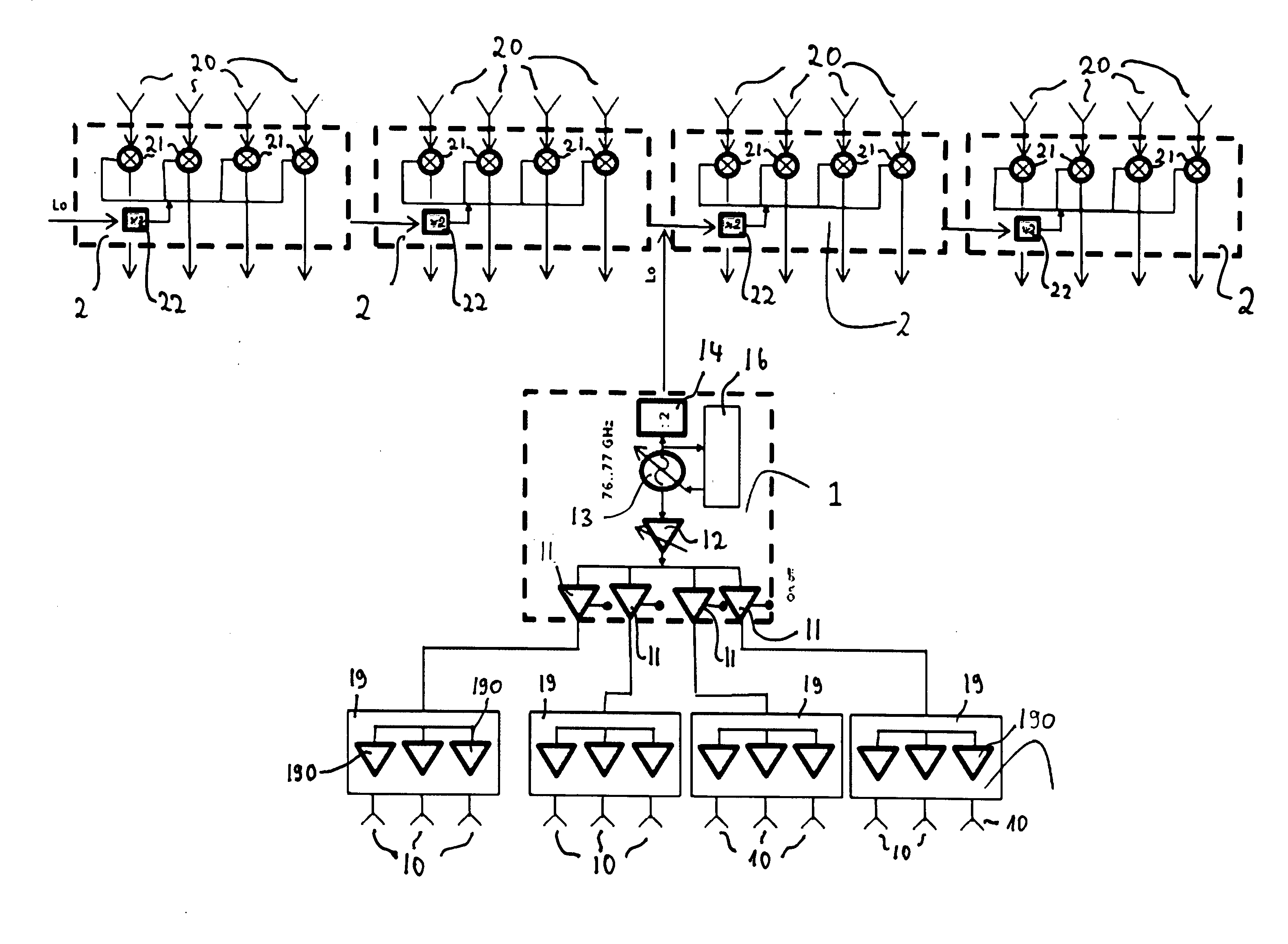
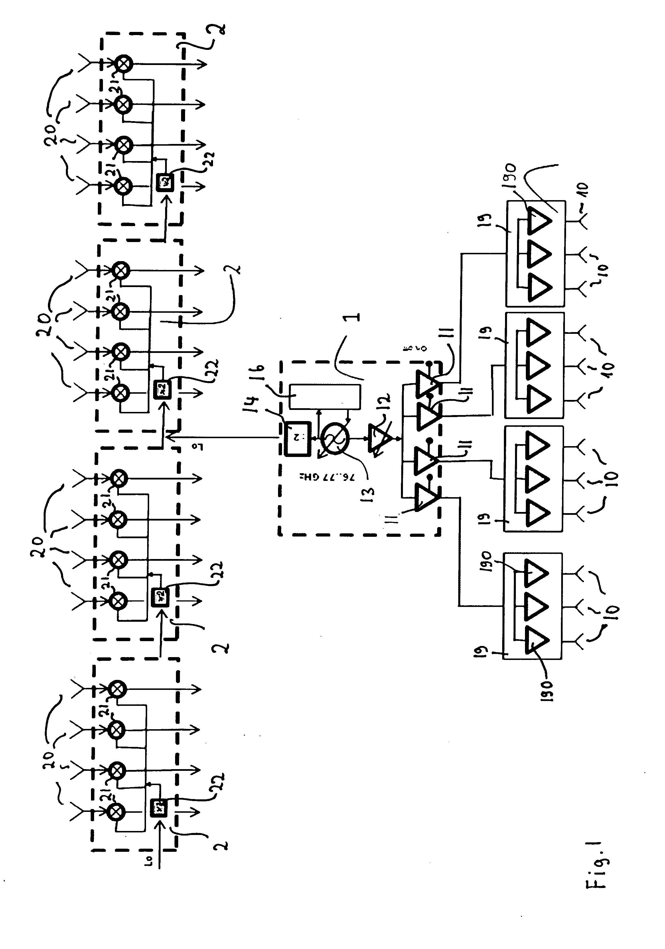
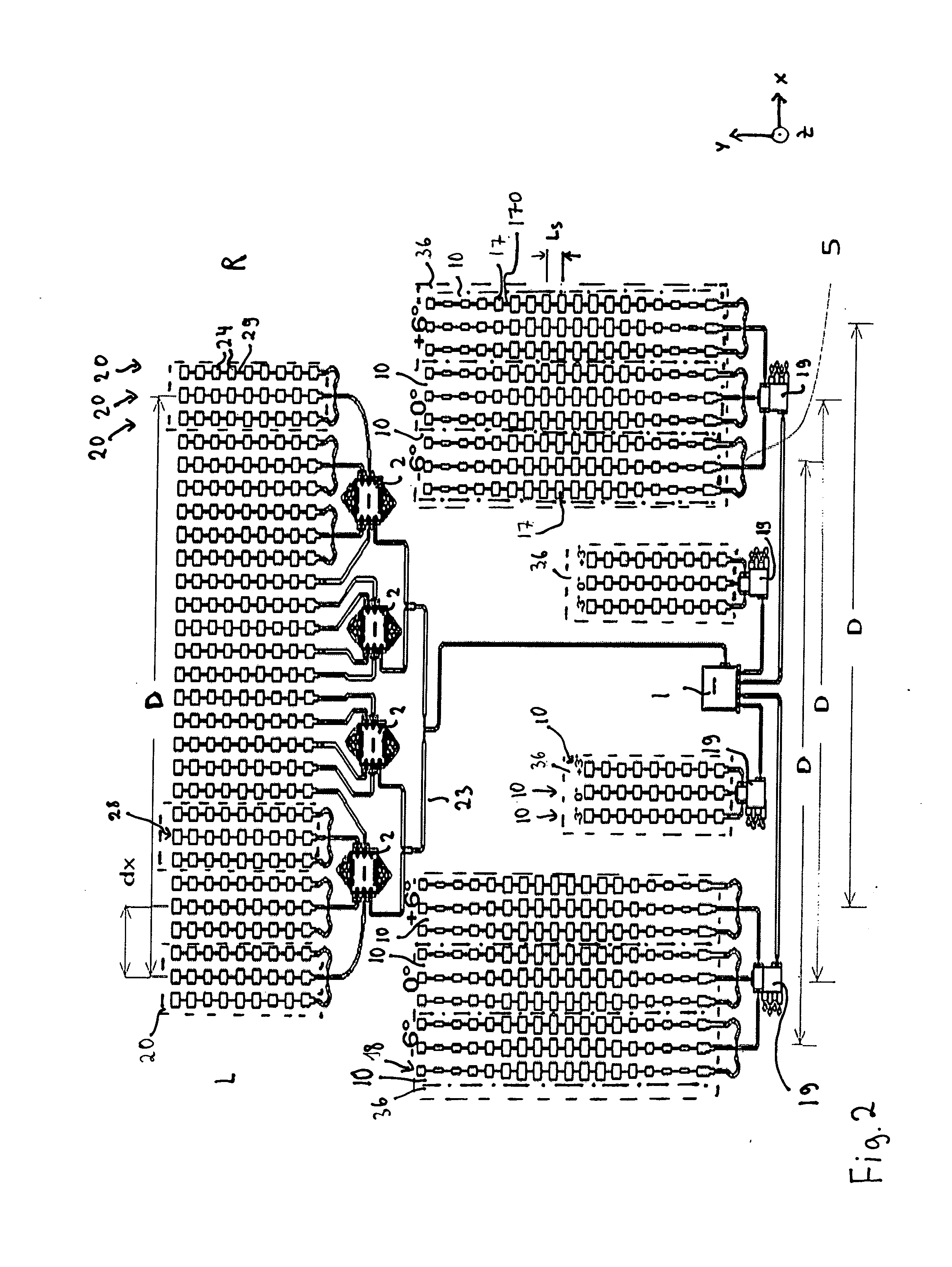
[0022]A device for determining a position of an object, in particular a moving object, comprising at least two switchable transmitting antenna arrays is provided. Here each transmitting antenna array has transmitting antennas which differ from one another as regards their main beam directions. A receiving antenna arrangement contains a plurality of receiving antennas which are arranged next to one another in a row running from left to right or next to one another in a row starting from a first and ending at a last receiving antenna.

[0023]The transmitting antenna arrays are arranged such that the distance betw...


PUM


Abstract

A device and a method for determining the position of an object, in particular of a moving object, in a three dimensional space is made available. Here the device comprises at least two switchable transmitting antenna arrays having different vertical beam alignments and a number of receiving antennas arranged in a row. The transmitting antennas are arranged spaced apart by a distance that corresponds to the distance between the outer phase centres of the receiving antennas. Otherwise the transmitting antennas can be positioned arbitrarily around the receiving antenna. The horizontal beam sweep over a wide angle range is implemented by the “digital beam forming” method. The vertical object position is measured by comparing the amplitude of the received signals with sequentially operated transmitting antennas having different vertical beam directions.

Description

BACKGROUND OF THE DISCLOSURE[0001]The invention relates to a method for increasing the angular resolution of imaging radar sensors with a limited available antenna aperture and a method for two-dimensional beam sweep.[0002]Millimetre wave radar sensors, e.g. for automotive applications, should have a compact and inexpensive construction. This means that the available surface for the antenna is to be kept as small as possible and the number of high frequency components should be minimised.[0003]On the other hand, the sensor should exhibit a high angular resolution which, however, requires a large antenna surface—a so-called aperture.[0004]This conflict of requirements is advantageously resolved by the following invention. The antenna aperture of the radar sensors can be reduced here almost by the factor of two while the angular resolution remains the same.[0005]A further requirement is recognition of the tail end of a traffic jam on the road. A distinction must be made here between s...

Claims


Application Information

Patent Timeline
Patent Type & Authority Applications(United States)
IPC IPC(8): G01S13/58G01S7/41G01S13/931
CPCG01S13/58G01S7/41G01S13/4445G01S13/422G01S13/931G01S7/032G01S13/34H01Q21/065G01S2013/9389H01Q21/22G01S2013/93275G01S7/2883
Inventor KOERBER, RICHARDHOEHNE, FELIX
Owner CRUISE MUNICH GMBH
Why Eureka
Try Eureka