Sensing Method And Related Device For Touch Panel

a touch panel and sensor technology, applied in the field of sensor method and related devices for touch panels, can solve the problems of insufficient space for multiple input devices in electronic products, inability to meet user demand, and inability to modify traditional input devices

Inactive Publication Date: 2014-10-16
NOVATEK MICROELECTRONICS CORP
View PDF5 Cites 17 Cited by
  • Summary
  • Abstract
  • Description
  • Claims
  • Application Information

AI Technical Summary

Benefits of technology

[0009]An integration circuit for a touch panel is disclosed. The touch panel comprises a plurality of sensing lines and a plurality of driving lines. The integration circuit comprises a control circuit, a switching unit, a plurality of multiplexer, an electromagnetic sensing unit and a capacitive sensing unit. The control circuit is used for controlling the plurality of sensing lines and the plurality of driving lines to sense a coordinate of an electromagnetic signal or a capacitive signal on the touch panel. The switching unit is coupled to the plurality of sensing lines and the plurality of driving lines, and used for controlling conductio

Problems solved by technology

However, the traditional input devices are not able to meet the user's demand and the electronic product does not have enough spaces for multiple inp

Method used


Image

  • Sensing Method And Related Device For Touch Panel
  • Sensing Method And Related Device For Touch Panel
  • Sensing Method And Related Device For Touch Panel

Examples


Embodiment Construction

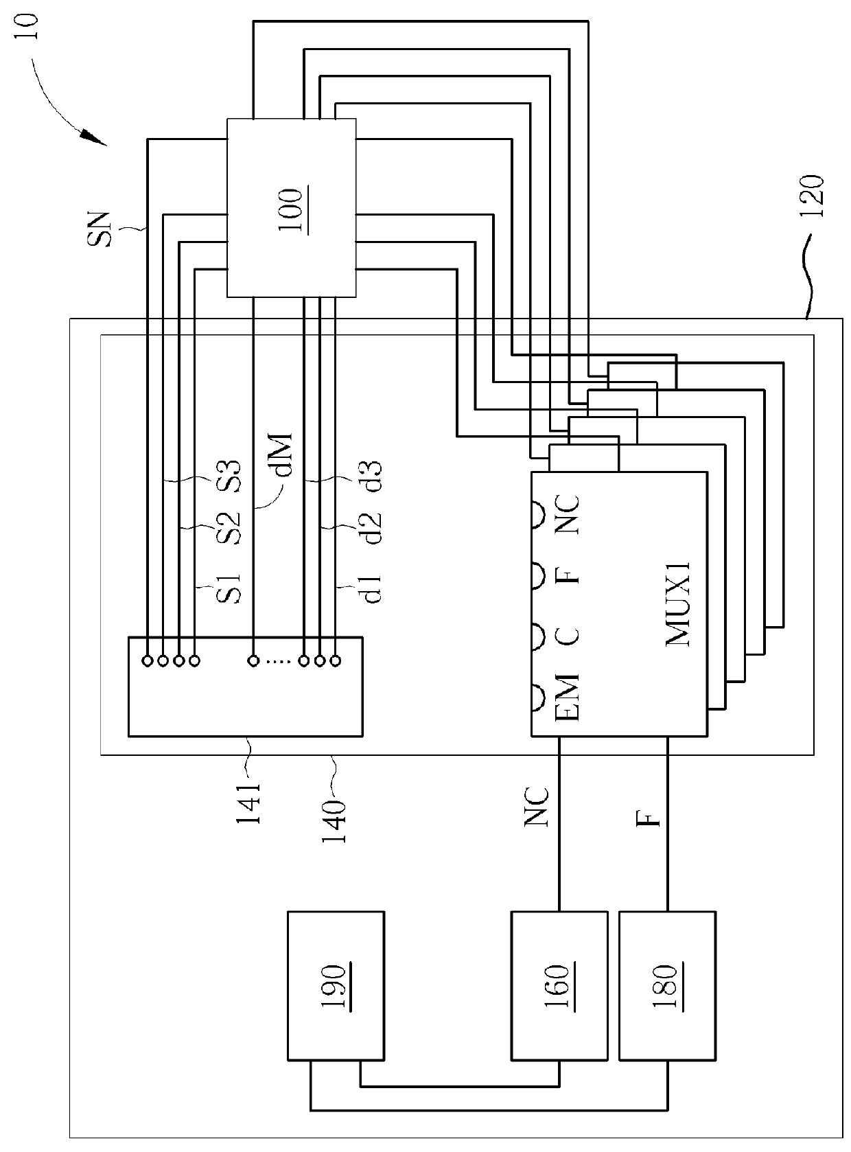
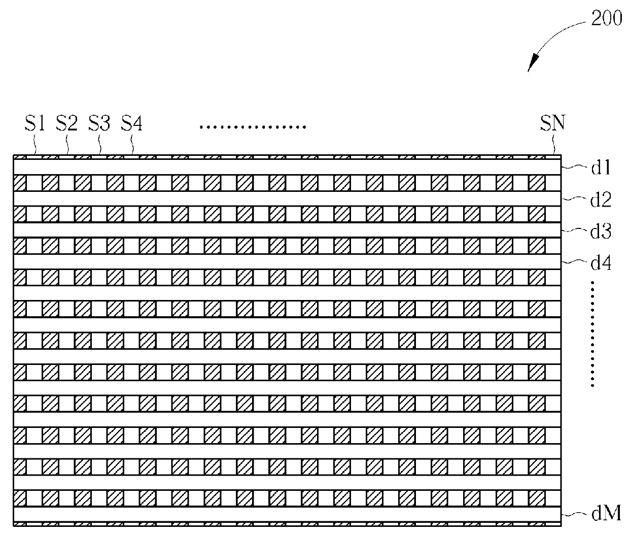
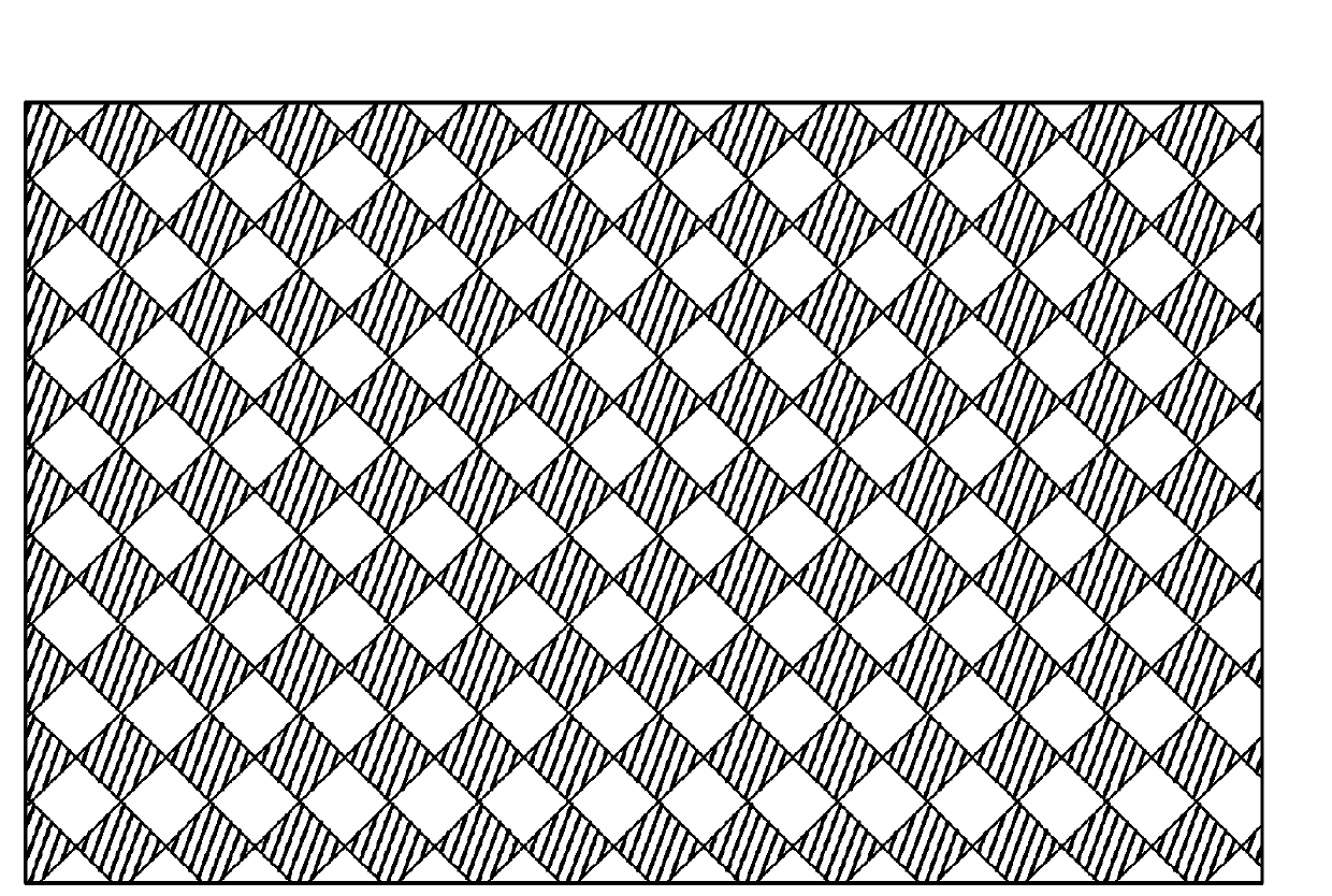
[0020]Please refer to FIG. 1, which is an exemplary schematic diagram of a touch panel 10. The touch panel 10 includes a sensor 100 and an integration circuit 120. The touch panel 10, preferably, is a capacitive touch panel or an Indium tin oxide (ITO) touch panel made of ITO. The sensor 100 includes multiple sensing lines S1, S2, S3, . . . , SN and multiple driving lines d1, d2, d3, . . . , dM. The sensor 100 is capable of sensing an electromagnetic signal SEM and a capacitive signal SC on the touch panel, generated by a user. Preferably, the sensor 100 is a capacitive sensor, which senses the X coordinate of the capacitor signal SC on the touch panel 10 through the sensing lines S1, S2, S3, . . . , SN and senses the Y coordinate of the capacitor signal SC on the touch panel 10 through the driving lines d1, d2, d3, . . . , dM. Please refer to FIGS. 2 and 3, which are schematic diagrams of a sensing pattern 200 and a sensing pattern 300 according to examples of the present disclosur...


PUM


Abstract

A sensing method for a touch panel is disclosed. The touch panel includes a plurality of sensing lines and a plurality of driving lines. The sensing method includes generating an electromagnetic signal or a capacitive signal; forming a plurality of first loops through the plurality of sensing lines to sense X coordinate of the electromagnetic signal on the touch panel and forming a plurality of second loops through the plurality of driving lines to sense Y coordinate of the electromagnetic signal on the touch panel when the electromagnetic signal is generated; sensing X coordinate of the capacitive signal through the plurality of sensing lines and sensing Y coordinate of the capacitive signal through the plurality of driving lines when the capacitive signal is generated.

Description

BACKGROUND OF THE INVENTION[0001]1. Field of the Invention[0002]The present invention relates to a sensing method and related device for a touch panel, and more particularly, to a method of integrating electromagnetic signal sensing and capacitive signal sensing on the touch panel and related device.[0003]2. Description of the Prior Art[0004]Since the technology has been evolving, there exist many types of input devices such as a keyboard, mouse, trackball, touch panel and etc., providing control on the electronic device for a user to execute programs or operations. The design trend for electronic devices is also towards small size, light-weight and all-in-one. However, the traditional input devices are not able to meet the user's demand and the electronic product does not have enough spaces for multiple input devices either.[0005]A touch panel integrates functions of a mouse, a keyboard and a graphic tablet and also features in low-power consumption and compact appearance so more a...

Claims


Application Information

Patent Timeline
IPC IPC(8): G06F3/044
CPCG06F3/044G06F3/046G06F2203/04106G06F3/04164G06F3/04166G06F3/0446
Inventor YEH, YUN-HSIANGLAI, CHIH-CHANG
Owner NOVATEK MICROELECTRONICS CORP
Why Eureka
Try Eureka