
Drain plug linkage device

a plug and plug-in technology, applied in water installations, washstands, constructions, etc., can solve the problems of affecting the operation of the linkage mechanism, the connection member is prone to rust, and the assembly is not easy enough

Active Publication Date: 2014-10-23
XIAMEN LOTA INT CO LTD
View PDF13 Cites 10 Cited by
  • Summary
  • Abstract
  • Description
  • Claims
  • Application Information

AI Technical Summary

Benefits of technology

The present invention is a drain plug linkage device that allows for easy and reliable assembly and disassembly of the pull rod, as well as relative position adjustment of the lever member and link rod. The device includes an adjustment mechanism that allows for low force adjustments and a pivot assembly that simplifies assembly and disassembly of the device. The technical effects of the invention include improved efficiency and convenience in assembly and disassembly of the drain plug linkage device.

Problems solved by technology

It is fairly difficult to assemble such a linkage mechanism, since a number of small components have to be mounted in a limited space.
Furthermore, the connecting member is prone to rust, which will be detrimental to operation of the linkage mechanism.
Moreover, the pull rod member of the linkage mechanism is mainly made from rigid rod pieces, which results in lack of degree of freedom during transition from a vertical lift movement of the pull rod to a vertical lift movement of the drain plug via the lever action.
In addition, difficulty occurs in mounting a locking nut by means of which the spherical part is directly and pivotably mounted in the pipe body of the discharge valve.
However, no positioning effect can be provided by the connection among the J-shaped portion of stem, the apertures of connector bar and the lever arm in the linkage assembly, such that an effective opening and closing movement of the drain stopper may not be realized by said linkage assembly.
Nevertheless, a considerable force for disengaging the snapping connection needs to be overcome, which results in, e.g., difficulty in adjusting the positions of the connecting bar relative to the pivot rod and also in disengaging the lift rod from the connecting bar, meanwhile causes wear of components in the linkage assembly easily, and shortens service life of the linkage assembly.
Moreover, a spherical body of the pivot rod in the linkage assembly is still directly mounted in a pipe via a locking nut, causing difficulty in assembly in the limited space.

Method used


Image

  • Drain plug linkage device
  • Drain plug linkage device
  • Drain plug linkage device

Examples


Embodiment Construction

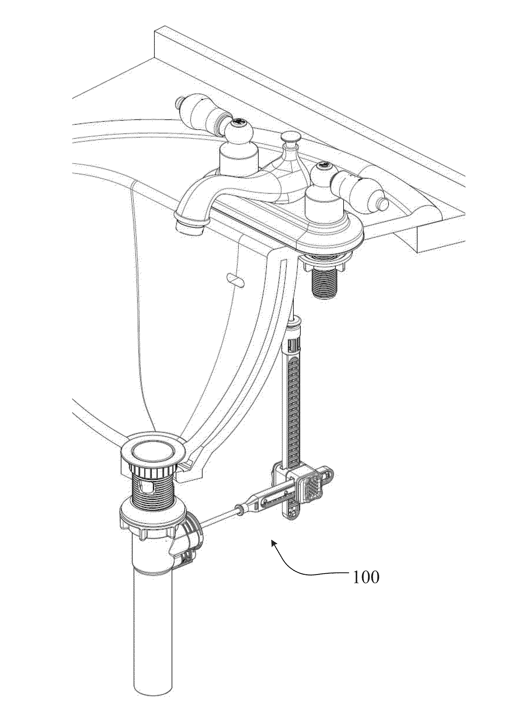
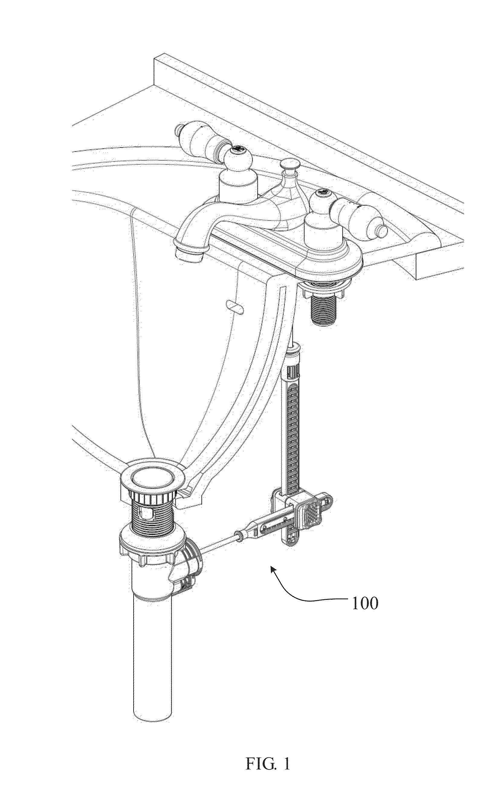
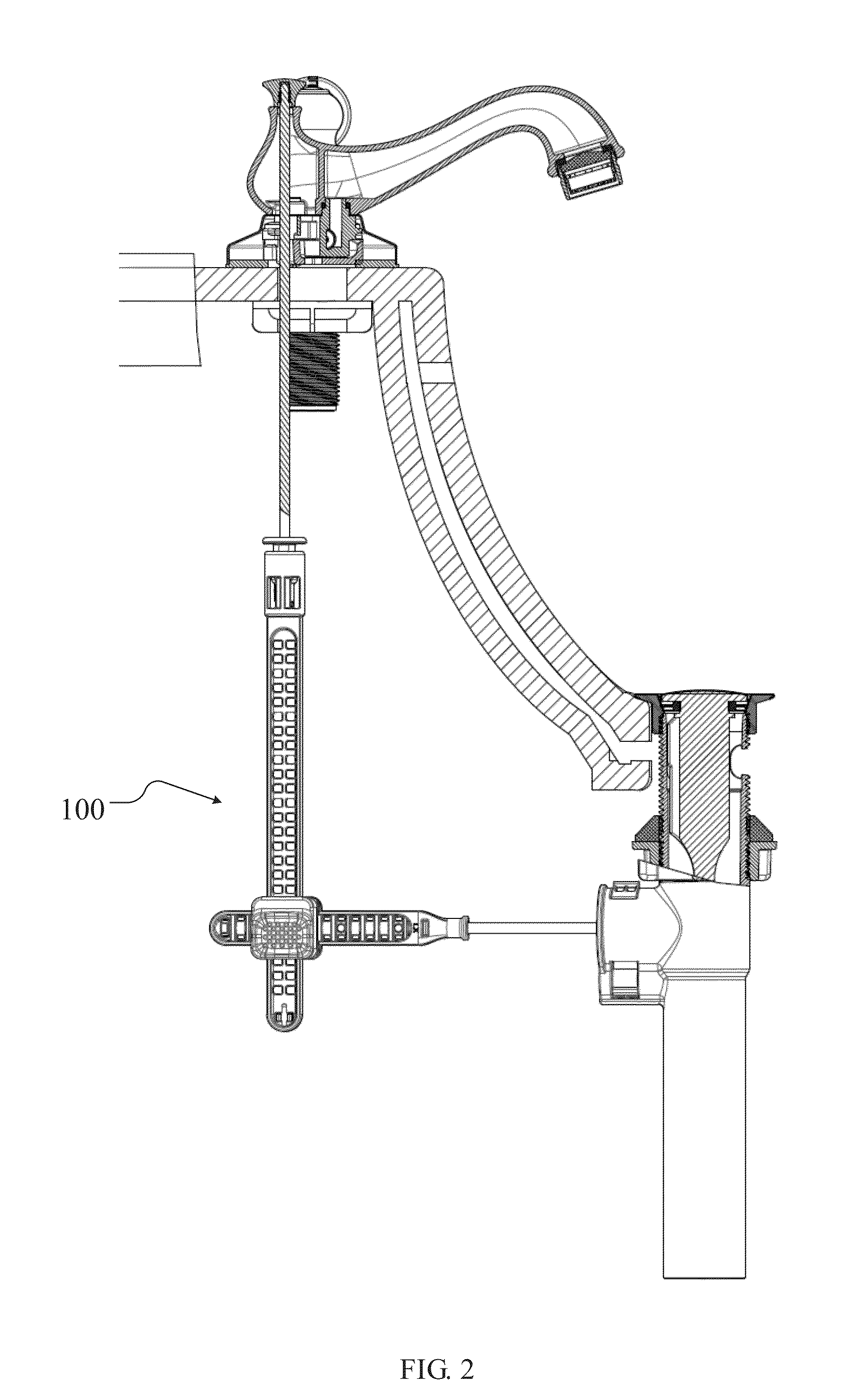
[0062]For a better understanding of the features, objects and effects of the present invention, exemplary embodiments of the present invention will be described with reference to the figures. Although the figures are provided to represent some embodiments of the present invention, the drawings are not required to be drawn in scale, and some features can be enlarged, removed or cross-sectioned to better illustrate the present invention. The term “in the drawing” or similar terms used herein do not necessarily refer to all the accompanying drawings or examples.

[0063]Some directional terms, such as “top”, “bottom”, “left”, “right”, “upwards”, “downwards” and other directional terms, used herein for describing the accompanying drawings will be understood to have their normal meaning and will refer to those directions as the drawings are normally viewed, and shall not be interpreted as a restriction to technical solutions in the appended claims.

[0064]The term “about” or “approximately” u...


PUM


Abstract

In the invention a drain plug linkage device (100) is provided, comprising: a drain plug (4) at least partially disposed in a pipe body (5); a pull rod assembly including a pull rod, a link rod (2) and a pull rod connector (9), wherein the link rod (2) at its upper end comprises a receiving portion, the pull rod connector (9) comprises a central hole and adapted to be snapped into the containing portion, and the pull rod at its bottom comprises a snap portion adapted to be snapped into the central hole; and a lever member (3) comprising a first end operatively connected to the link rod (2), and a second end extending into the pipe body (5) and configured to operate the drain plug (4); wherein the receiving portion comprises an expansion portion (22) for expanding the central hole, and the pull rod connector (9) is configured, when snapped into the receiving part, to be movable between a position where the central hole is unexpanded and a position where the central hole is expanded by the expansion portion (22).

Description

CROSS REFERENCE TO RELATED APPLICATIONS[0001]This application claims priority under 35 U.S.C. §119 to following Chinese Patent application no. CN 201310134232.1, filed Apr. 17, 2013, the contents of which are incorporated herein by reference thereto.FIELD OF THE INVENTION[0002]The present invention relates particularly to the technical field of drain, a drain device for example for bathroom, tub, washbasin or hand-washing sink, and more particularly to a drain plug linkage device which can be assembled and adjusted rapidly.BACKGROUND OF THE INVENTION[0003]A water discharger, also referred to as drain device, is proposed for storing or discharging water in containers such as bathroom, tub, washbasin or hand-washing sink. Such drain device is generally in form of a drain plug linkage device. For instance, in a prior art drain device, the container is in communication with a drainpipe through an outlet, and a drain plug is disposed adjacent to the outlet and connected with one end of a...

Claims


Application Information

Patent Timeline
Patent Type & Authority Applications(United States)
IPC IPC(8): A47K1/14
CPCA47K1/14E03C1/2302
Inventor YE, LIMINGZHOU, JIANPINGZHANG, YAN
Owner XIAMEN LOTA INT CO LTD
Learn More