Pneumatic tire

Inactive Publication Date: 2014-10-23
TOYO TIRE & RUBBER CO LTD
View PDF3 Cites 11 Cited by
  • Summary
  • Abstract
  • Description
  • Claims
  • Application Information

AI Technical Summary

Benefits of technology

[0014]According to the invention, in a state where the pneumatic tire is filled with a regulated internal pressure, as the thickness of the intermediate land sections is greater than the thickness of the center land section and the radius of a peak section of the intermediate land sections is equal to or smaller than the radius of a peak section of the center land section, it is possible to increase th

Problems solved by technology

However, if the center portion of the tread section in the tire width direction swells outwardly in the tire radial direction as disclosed in JP-A-2007-69665, JP-A-2005-263180, and JP-A-2005-319890, there is a problem in that the operation stability is enhanced by enlargement of a ground contact area, but a around contact length of the center portion in the tire width direction becomes relatively large compared with the other sectio

Method used


Image

  • Pneumatic tire
  • Pneumatic tire
  • Pneumatic tire

Examples


examples

[0038]Hereinafter, examples of the invention will be more specifically described, but the invention is not limited to the examples.

[0039]Pneumatic radial tires (195 / 65R15) for passenger cars of Examples 1 and 2 and Comparative Examples to 3 were manufactured for a test.

[0040]The respective tires were the same in a basic tread pattern and a tire inner structure, and were manufactured by changing the respective specifications shown in Table 1.

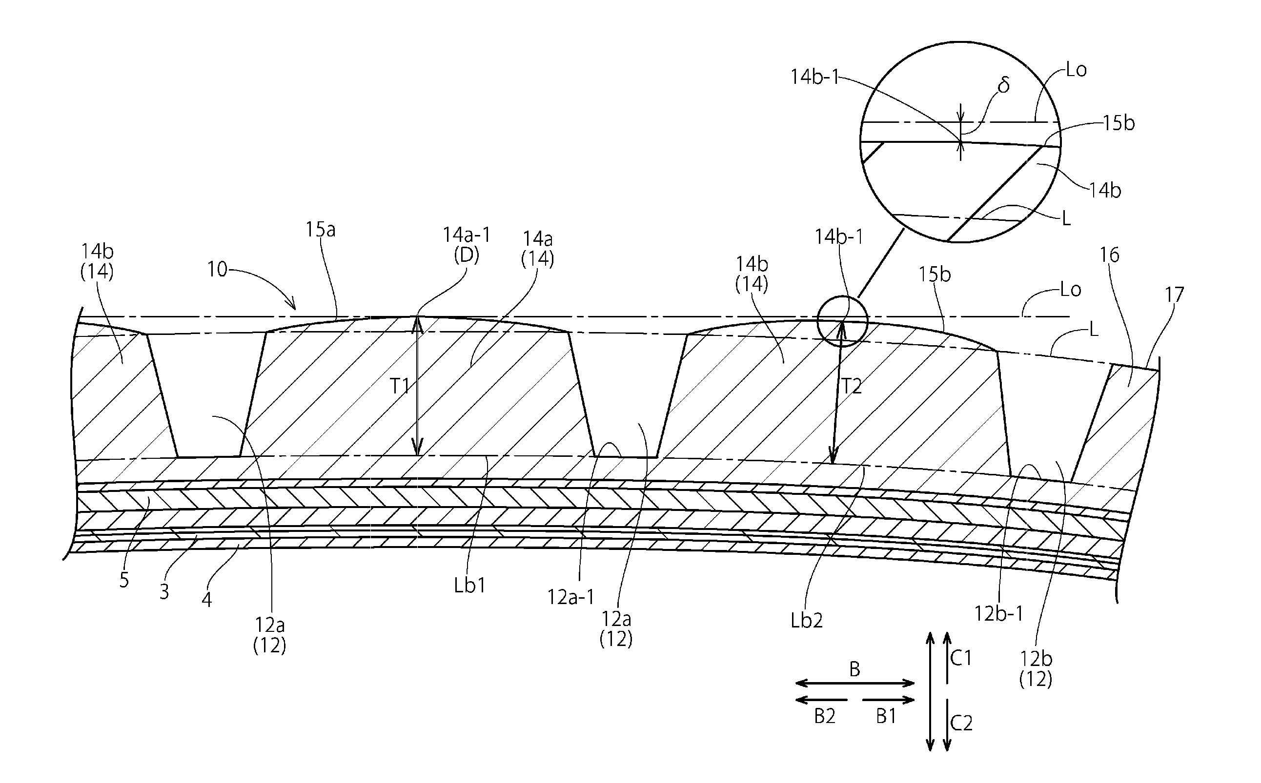
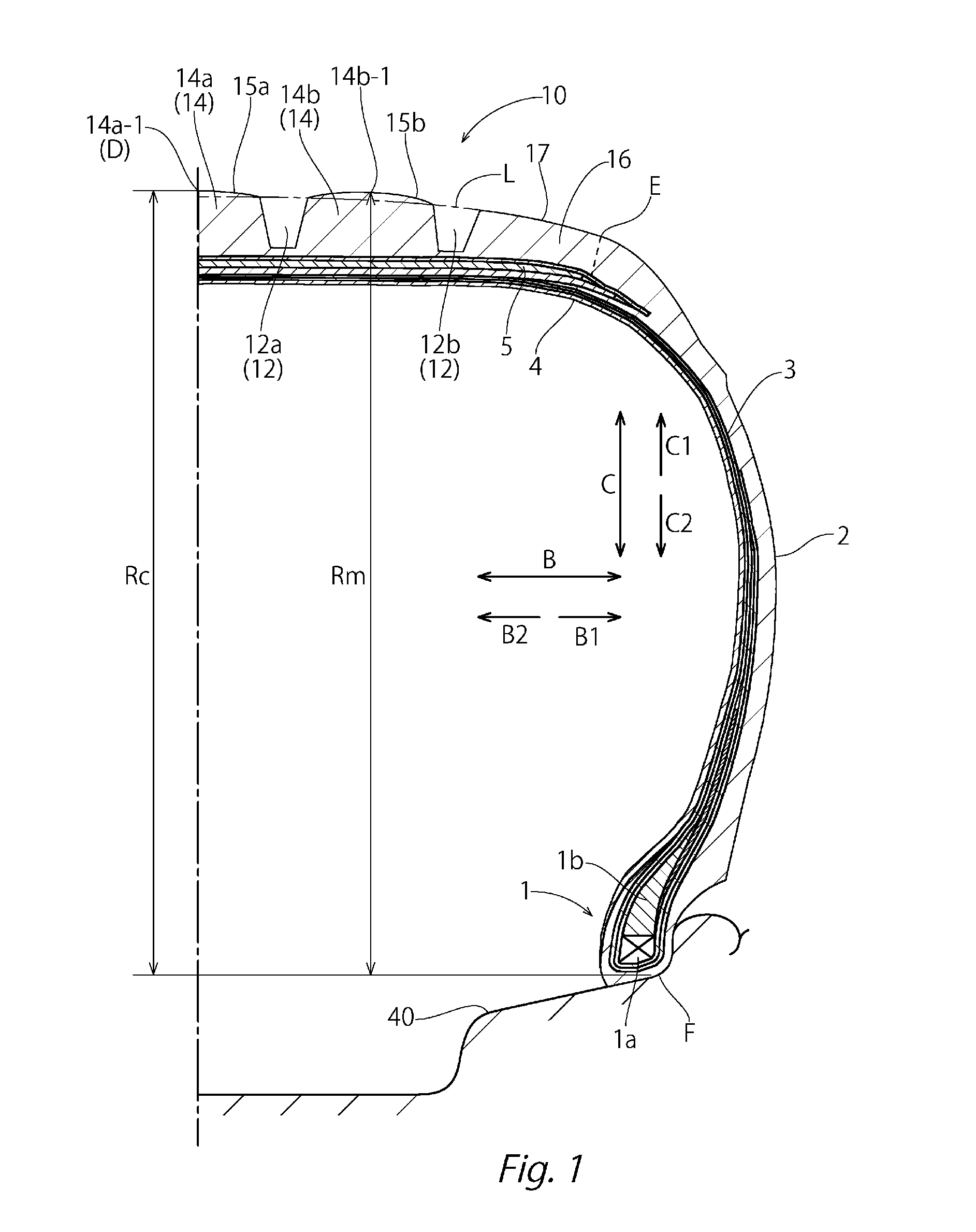
[0041]Specifically, Examples and 2 are examples of a pneumatic tire in which the center land section 14a and the intermediate land sections 14b swell outwardly from the basic tread profile line L so that the thickness T2 of the intermediate land sections 14b is greater than the thickness T1 of the center land section 14a and the radius of the peak section 14b-1 of the intermediate land sections 14b is equal to or smaller than the radius of the peak section 14a-1 of the center land section 14a (that is, the height difference δ (=Rc−Rm) between the...


PUM


Abstract

A pneumatic tire is provided with a center land section formed between center main grooves, a pair of intermediate land sections formed between shoulder main grooves and the center main grooves, and a pair of shoulder land sections formed on the outside of the shoulder main grooves in a tire width direction. The center land section and the intermediate land sections swell outwardly in a tire radial direction from a basic tread profile line that smoothly connects ground contact surfaces of the pair of shoulder land sections. The radius of a peak section of the intermediate land sections is equal to or smaller than the radius of a peak section of the center land section, and the thickness of the intermediate land sections is greater than the thickness of the center land section.

Description

BACKGROUND OF THE INVENTION[0001]1. Field of the Invention[0002]The present invention relates to a pneumatic tire.[0003]2. Background Art[0004]Performances such as an operation stability performance and a high fuel efficiency are demanded in a pneumatic tire. In order to improve these performances, a variety of techniques have been proposed.[0005]For example, JP-A-2007-69665 discloses a pneumatic tire in which a center portion of a tread section swells outwardly in a tire radial direction. This pneumatic tire employs a tire profile in which only the center portion of the thread section is in contact with the ground under a low load such as normal traveling.[0006]JP-A-2005-263180 discloses a pneumatic tire including a tread section provided with plural circumferential main grooves that extend in a tire circumferential direction and a rib formed between the circumferential main grooves, in which the rib swells outwardly in a radial direction from an arc-shaped contour line L of a radi...

Claims


Application Information

Patent Timeline
IPC IPC(8): B60C11/13
CPCB60C11/1376B60C11/0306
Inventor TAKAHASHI, SOUICHI
Owner TOYO TIRE & RUBBER CO LTD
Why Eureka
Try Eureka