
Airtightness maintaining structure for butterfly valve

a technology of air tightness and maintaining structure, which is applied in the direction of valve housing, combustion air/fuel air treatment, machines/engines, etc., can solve problems such as deterioration of engine performan

Active Publication Date: 2014-10-23
AISIN SEIKI KK
View PDF1 Cites 15 Cited by
  • Summary
  • Abstract
  • Description
  • Claims
  • Application Information

AI Technical Summary

Benefits of technology

The present invention relates to a seal assembly for a rotating shaft. The invention helps to maintain airtightness by reducing fluid leakage from the periphery of the rotating shaft. This is achieved by using a rotating shaft seal which moves from the high fluid pressure side to the low fluid pressure side, allowing the force generated by the fluid to act on the seal. The seal is designed to always move to the optimum position even when the high fluid pressure side is switched. Additionally, the seal is positioned between the tapered portion of the pivotably supporting member and the tapered surface of the rotating shaft, reducing the space needed for the seal and further reducing fluid leakage.

Problems solved by technology

If the leakage of the air between the two sections is increased in the closed valve state, the expected resonance frequency is not generated in the intake system of the engine and the supercharging effect is degraded, resulting in the deterioration of the performance of the engine.

Method used


Image

  • Airtightness maintaining structure for butterfly valve
  • Airtightness maintaining structure for butterfly valve
  • Airtightness maintaining structure for butterfly valve

Examples


first embodiment

[0039

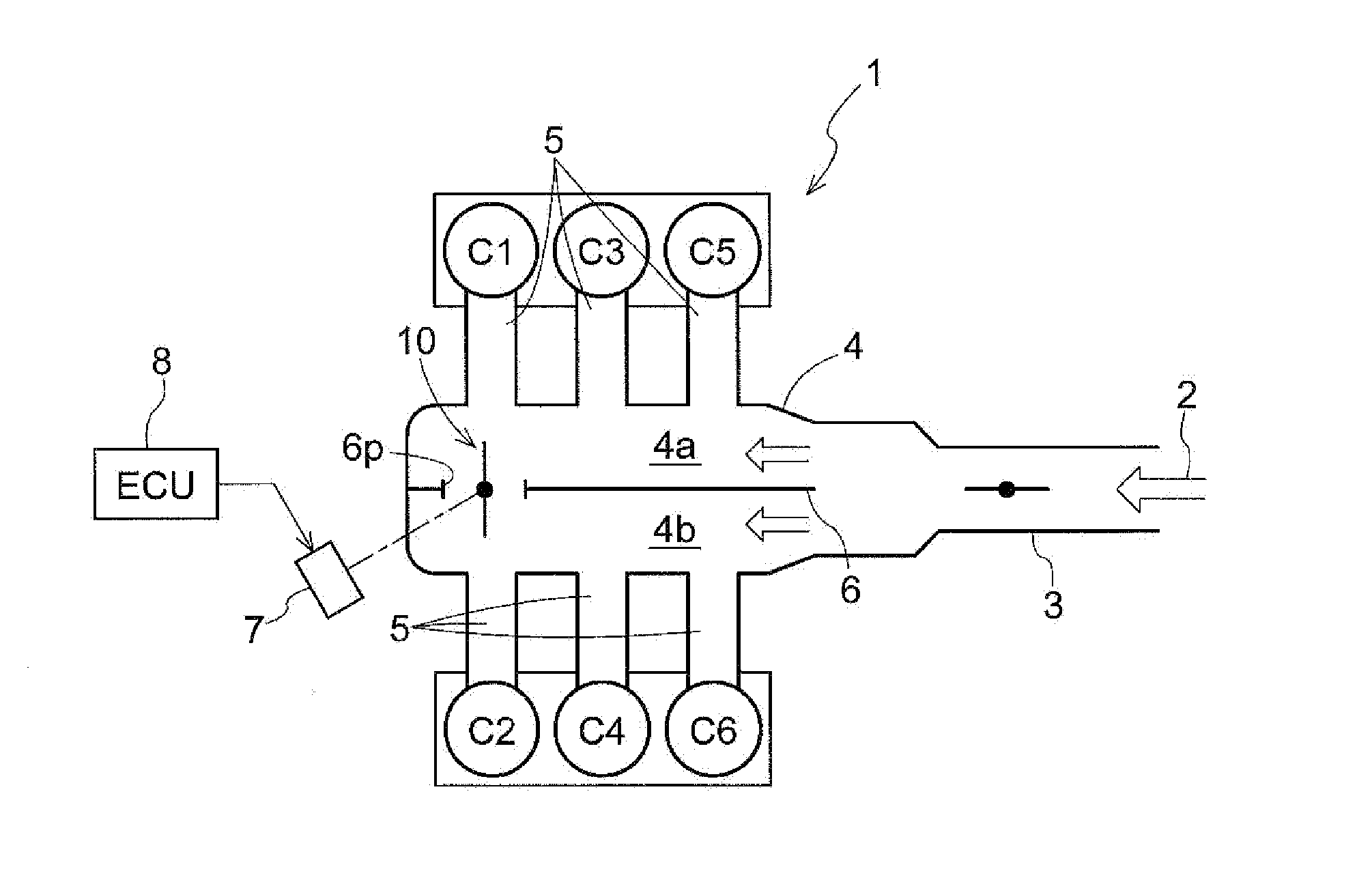
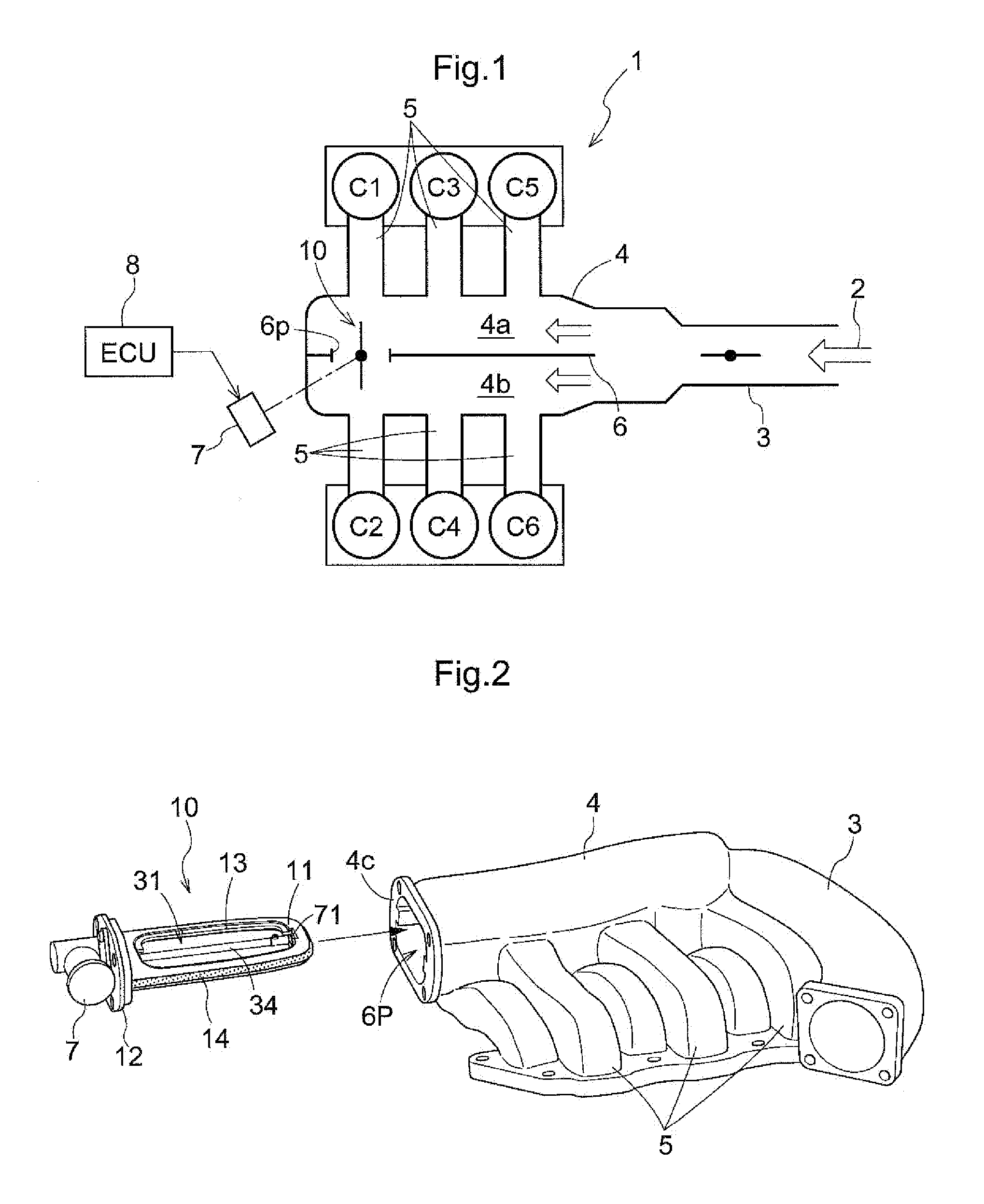
[0040]Hereinafter, embodiments for implementing the present invention will be described with reference to the drawings. FIG. 1 is a schematic view illustrating the relation between an intake system 1 of a V-6 cylinder engine and six cylinders C1 to C6. The intake system 1 has an intake passage 3 into which fluid (air) 2 is supplied through an air filter (not shown) and a surge tank 4 that is in communication with the intake passage 3. The intake passage 3 is provided with a throttle valve. The surge tank 4 is divided into a first surge section 4a and a second surge section 4b by a partition 6. In the first surge section 4a shown in the upper part of FIG. 1, the cylinder C1, cylinder C3 and cylinder C5 extend via intake pipes 5, and in the second surge section 4b shown in the lower part, the cylinder C2, cylinder C4 and cylinder C6 extend via the intake pipes 5.

[0041]FIG. 2 is a perspective view illustrating a specific shape of the intake system 1. A portion of the partition 6 i...

second embodiment

[0070

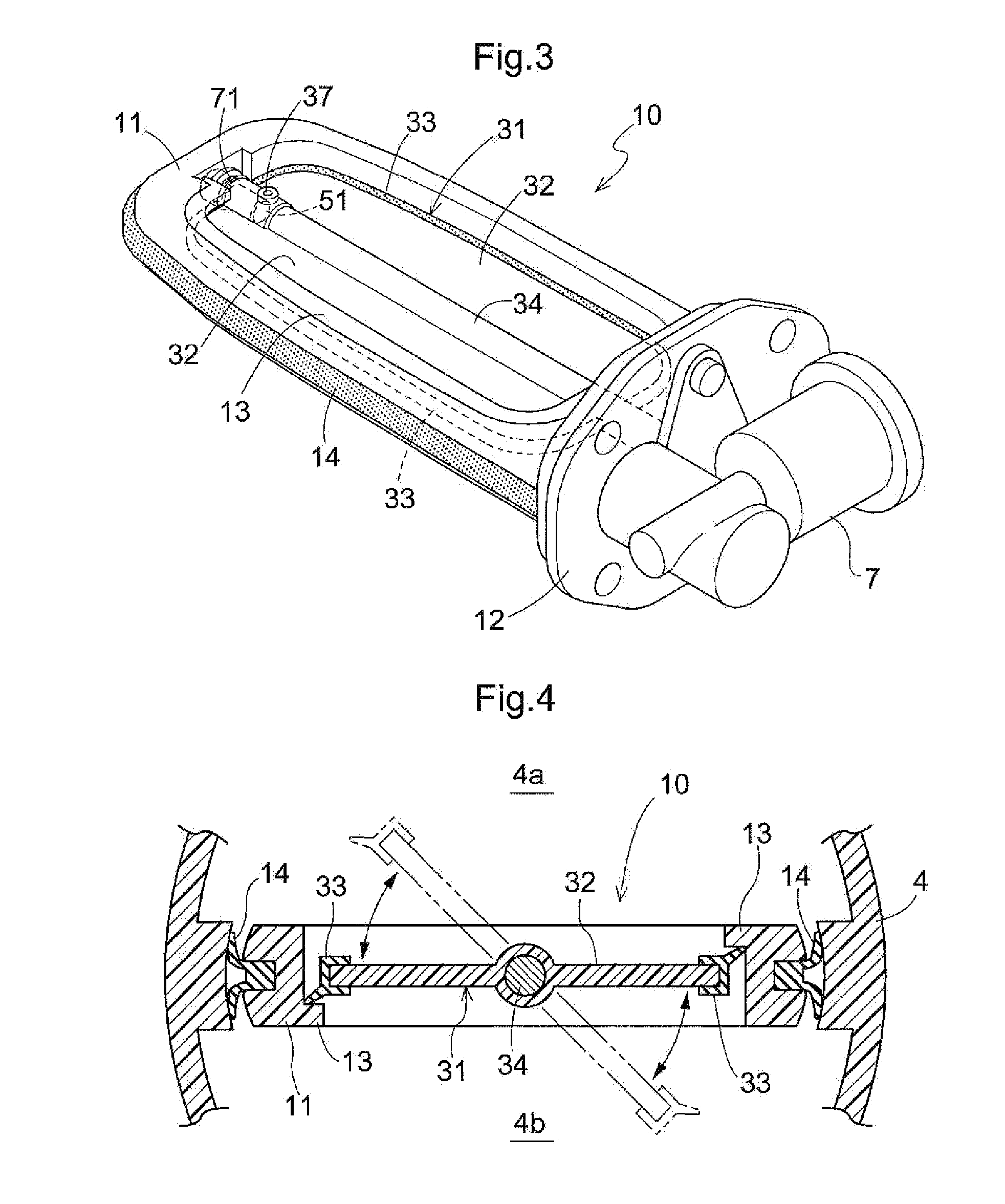
[0071]FIGS. 10A and 10B show a second embodiment of the present invention. FIG. 10A is a cross-sectional view illustrating a state of the rotating shaft seal 81 when there is no difference between the pressure in a first surge section 4a and the pressure in a second surge section 4b. FIG. 10B is a cross-sectional view illustrating a state of the rotating shaft seal 81 when the fluid pressure in the first surge section 4a becomes high and the fluid pressure in the second surge section 4b becomes low. In this embodiment, the same description as in the first embodiment has been omitted. A rotating shaft seal 81 of this embodiment is different from the rotating shaft seal 71 of the first embodiment in that the cross-section obtained by cutting the rotating shaft seal 81 at a plane that crosses the central axis thereof has a circular shape. This is because, in this embodiment, not only the pivotably supporting member 51 has the tapered portion 51 b but also the end surface 35 of the...


PUM


Abstract

An airtightness maintaining structure for a butterfly valve includes a valve element having a rotating shaft and a valve body, a rotation supporting portion having a pivotably supporting member that fits onto the rotating shaft and pivotably supports the rotating shaft, and a rotating shaft seal arranged to contact in a fitting state both an end surface of a member on an outer radial and a surface of a member on an inner side either the rotation shaft or the pivotably supporting member and has an annular portion. In a closed valve state of the valve element, the rotating shaft seal moves radially due to a pressure difference between a high fluid pressure acting on one side of the valve element and a low fluid pressure acting on the other side and contacts both the valve element and the rotation supporting portion on the high fluid pressure side.

Description

TECHNICAL FIELD[0001]The present invention relates to a structure in which the leakage of fluid from the periphery of a rotation supporting portion for supporting a rotating shaft of a butterfly valve is reduced to maintain airtightness.BACKGROUND ART[0002]An intake system having a port and a surge tank in a multiple cylinder internal combustion engine of a car or the like is provided with a partition that divides the inside of the surge tank into two sections and a butterfly valve is attached to a position in which, for example, a portion of the partition is cut out. A butterfly valve includes a valve element that is switched to a state where the two sections divided by the partition are in communication (hereinafter, referred to as an “open valve state”) or a state where the two sections are partitioned (hereinafter, referred to as a “closed valve state”) by a rotation, a valve body that supports the valve element, and a sealing material for sealing between the inner circumferenti...

Claims


Application Information

Patent Timeline
Patent Type & Authority Applications(United States)
IPC IPC(8): F02D9/10F16K1/226
CPCF16K1/2268F02D9/106F02B27/0247F02M35/10255F02B27/0273F02M35/10065F16K41/046F16K41/066F16K1/2261F16K27/0218Y02T10/12F16K41/00F16J15/24F16K1/226
Inventor KATO, MASAYUKIISHII, MASATO
Owner AISIN SEIKI KK
Learn More