
In relation to a lens system for a camera

a technology of lens system and camera, applied in the direction of image enhancement, electrical apparatus casing/cabinet/drawer, instruments, etc., can solve the problems of difficult to achieve, user difficulty, attention of people in the scene, etc., and achieve the effect of improving usability

Inactive Publication Date: 2014-10-23
HAMPTON MARK ROSS
View PDF10 Cites 109 Cited by
  • Summary
  • Abstract
  • Description
  • Claims
  • Application Information

AI Technical Summary

Benefits of technology

The invention is about a device that improves the quality of images captured by a camera. It uses a correction function to adjust the image data to enhance the overall quality of the image. The device includes a light pipe that channels light from one end to another without losing its brightness. The light pipe can be rigid or flexible depending on the desired angling of the inlet to the outlet. The technical effects of the invention are improved image quality and flexibility in light direction.

Problems solved by technology

A disadvantage of this is that the attention of people in the scene may be drawn to the camera and this may distract them from the activity they are engaged.
Furthermore, in some instances, the photographer may wish to take a photograph of a scene without the people noticing, for example in order to capture natural and uninhibited shots of people, as is the case with street photography.
This may be difficult to achieve if the people in the scene are aware of the orientation of the camera, and as a result, they may end up posing or looking into the camera, or alternatively they may become self-conscious and attempt to hide from the camera.
However the majority of existing camera systems cause difficulties for a user when they wish to frame high or low angle shots.
A similar issue is present in respect of high angle shots where the camera is to be positioned high above a user's head, preventing a user from easily viewing the cameras display screen to effectively frame the shot.
However, this product is only available for cameras with lens threads of 52 mm, 55 mm and 58 mm—which are typical sizes for DSLR cameras.
Hence, a disadvantage of this product is that it is not able to be used for cameras that lack a lens thread, for example those found on mobile phones or electronic tablets.
However, this product is also not suitable for the small cameras found on most mobile electronic devices as these cameras typically lack a lens thread.
Furthermore, the devices described in GB 2,394,552 are large relative to the size of the camera, and hence they cannot generally be used with most mobile electronic devices.
Furthermore, the angle of view in each direction is restricted because the camera's original angle of view is shared by three different fields.
However, a disadvantage of tilt screens is that the tilt screen requires the mobile device to be designed with this in mind, and adds complexity and cost to the manufacturing of the mobile device.
However, a disadvantage of such tilting cameras is that they only modify the inclination of the camera and do not provide the camera with the ability to take photos to the left or right relative to the original direction of the camera's field of view.
However, these attachments can be relatively large compared to the mobile device.
They also reduce the resolution of the image to a point where they are not well suited to taking still images.
However the cameras provided in these devices do not incorporate high-quality optical elements and are not optimised or specifically adapted for photographic applications.
However these light sources can only function as a flash when a photograph is taken along the same optical axis as the camera provided.

Method used


Image

  • In relation to a lens system for a camera
  • In relation to a lens system for a camera
  • In relation to a lens system for a camera

Examples


Embodiment Construction

[0177]FIGS. 1-10 show the implementation of one embodiment of the invention when arranged to operate in conjunction with the camera of a mobile phone.

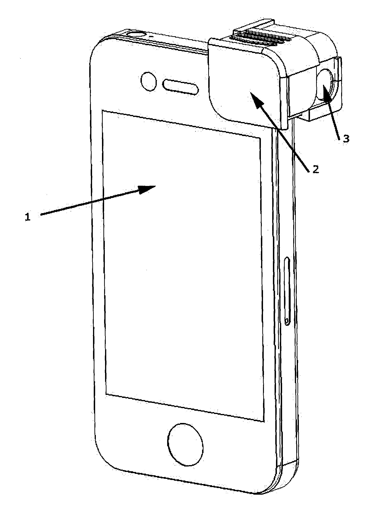
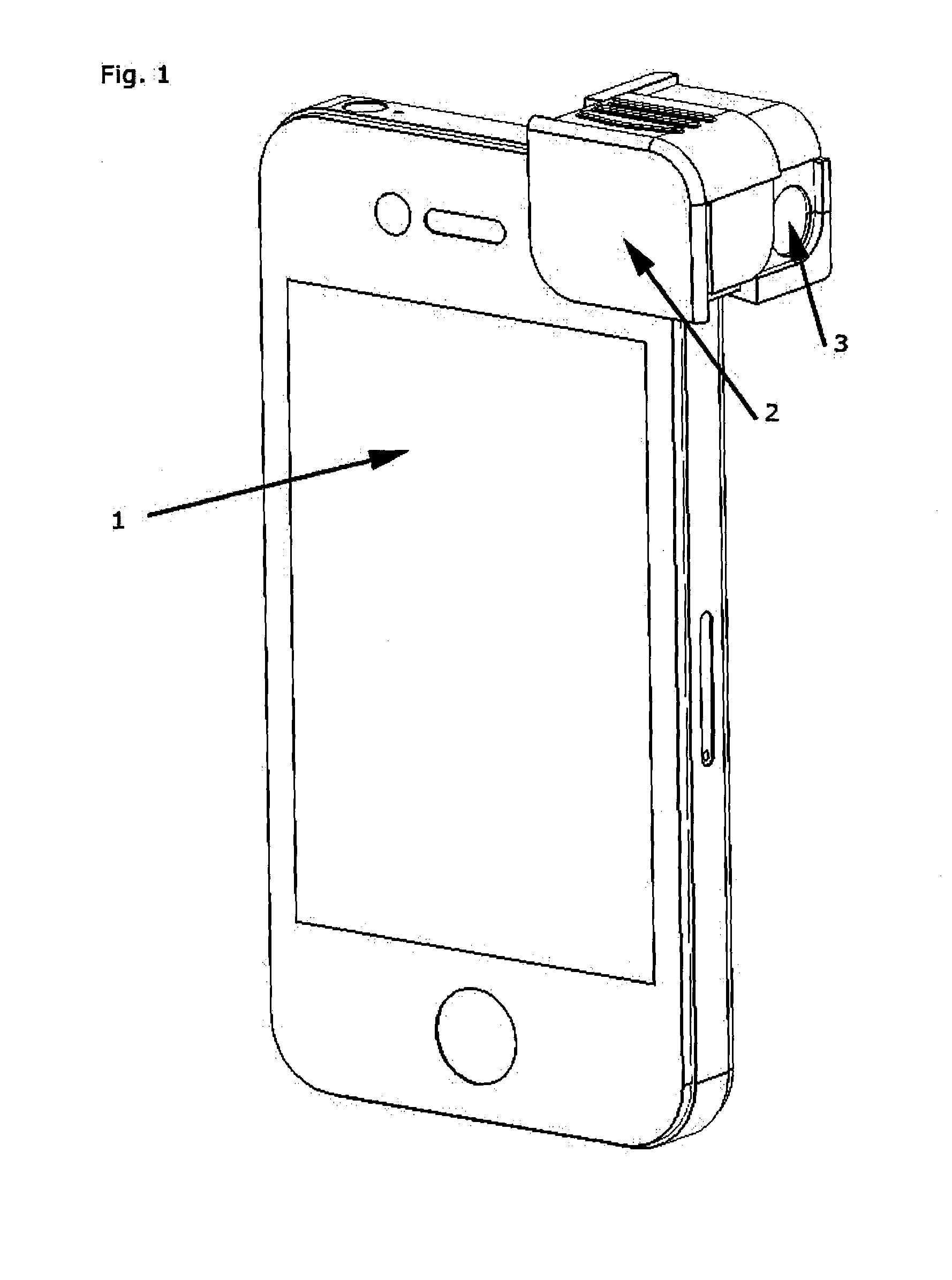
[0178]Having regard to FIG. 1, there is shown a lens system for a camera.

[0179]The lens system includes a housing 2 which is attachable to a camera incorporated within a mobile phone 1.

[0180]The housing 2 includes an optical system which is adapted to change the direction of the field of view of the camera associated with the mobile phone 1. The optical system 3 includes a lens which is oriented at a 90 degree angle relative to the optical axis of the mobile phone camera.

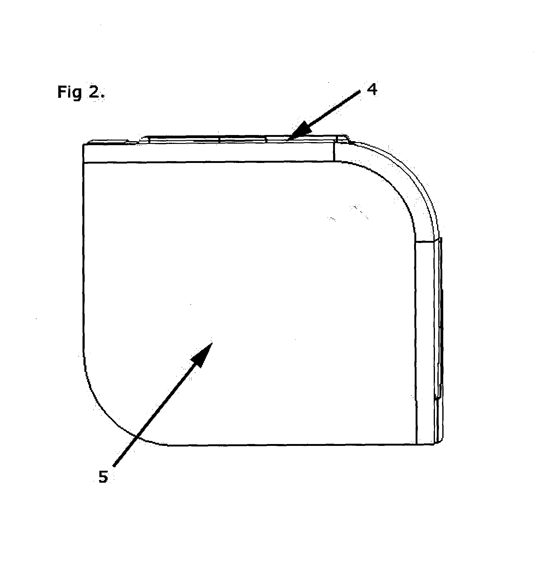
[0181]Having regard to FIG. 2, there is shown a front view of the housing 2. This serves to hold the housing 2 in place on the mobile phone. The front of the housing 5 and top 4 are visible.

[0182]Having regard to FIG. 3, there is shown a side view of the housing 2. The front of the housing 7 and top 6 are visible, as is an objective lens 8 which is aligned with the sce...


PUM


Abstract

Disclosed is a lens system for removable connection to a portable programmable device which includes a camera. This lens system can be arranged in various embodiments to modify the field of view experienced by this camera, and in specific embodiments can modify the direction of this cameras field of view. The device can also be used to provide software capable of executing on a portable programmable device, in addition to providing a light pipe to redirects light used as a photographic flash in applications where it modifies the direction of view of a camera.

Description

TECHNICAL FIELD[0001]This invention relates to improvements in and in relation to lens system for a camera. In particular embodiments, the invention can provide a lens system for a camera which changes the direction of the field of view of the camera.[0002]The invention may be particularly suitable for attachment to, or incorporation within, portable programmable devices devices that include a camera, such as for example, mobile phones, smartphones, laptops, and mobile computers or electronic tablets such as iPads®.[0003]However, it is to be understood and appreciated that the invention may also have other applications and / or uses. The prior art and possible applications of the invention, as discussed below, are therefore given by way of example only.BACKGROUND ART[0004]Digital cameras are well known. Many electronic devices also typically include digital cameras, for example mobile electronic devices such as mobile phones and electronic tablets.[0005]When using a digital camera, in...

Claims


Application Information

Patent Timeline
IPC IPC(8): G02B17/08H04N5/262G06T5/00
CPCG02B17/08H04N5/2628G06T5/001G06F1/1686G03B17/565G03B17/08H04B1/3888A45C2011/002G06F2200/1633G06F1/1626A45C11/00H05K5/03G06T5/00H05K5/0217
Inventor HAMPTON, MARK ROSS
Owner HAMPTON MARK ROSS
Learn More